Measuring endoscope system

a technology of measuring endoscope and endoscope, which is applied in the field can solve the problems of annoyance for users, endoscope drawbacks, and the performance of conventional measuring endoscope system, and achieve the effect of improving the maneuverability of measuring endoscope system in measurement and inspection efficiency

Active Publication Date: 2006-05-23
EVIDENT CORP
View PDF7 Cites 23 Cited by
  • Summary
  • Abstract
  • Description
  • Claims
  • Application Information

AI Technical Summary

Benefits of technology

[0019]An object of the present invention is to provide a measuring endoscope system capable of preventing implementation of a measuring technique not associated with an optical adaptor, and performing a measurement associated with an optical adaptor through simple handling. Thus, the present invention attempts to improve the maneuverability of a measuring endoscope system in measurement and the efficiency thereof in inspection.

Problems solved by technology

However, the measuring endoscope system described in the Japanese Unexamined Patent Application Publication No. 10-248806 and the length measuring optical adaptor for endoscopes described in the Japanese Unexamined Patent Application Publication No. 60-237419 have drawbacks described below.
For this reason, there is a fear that the conventional measuring endoscope system may have the performance thereof deteriorated.
Therefore, the conventional measuring endoscope has a drawback that handling a user have to perform for measurement is so complex as to annoy the user.

Method used


Image

  • Measuring endoscope system
  • Measuring endoscope system
  • Measuring endoscope system

Examples


first embodiment

(First Embodiment)

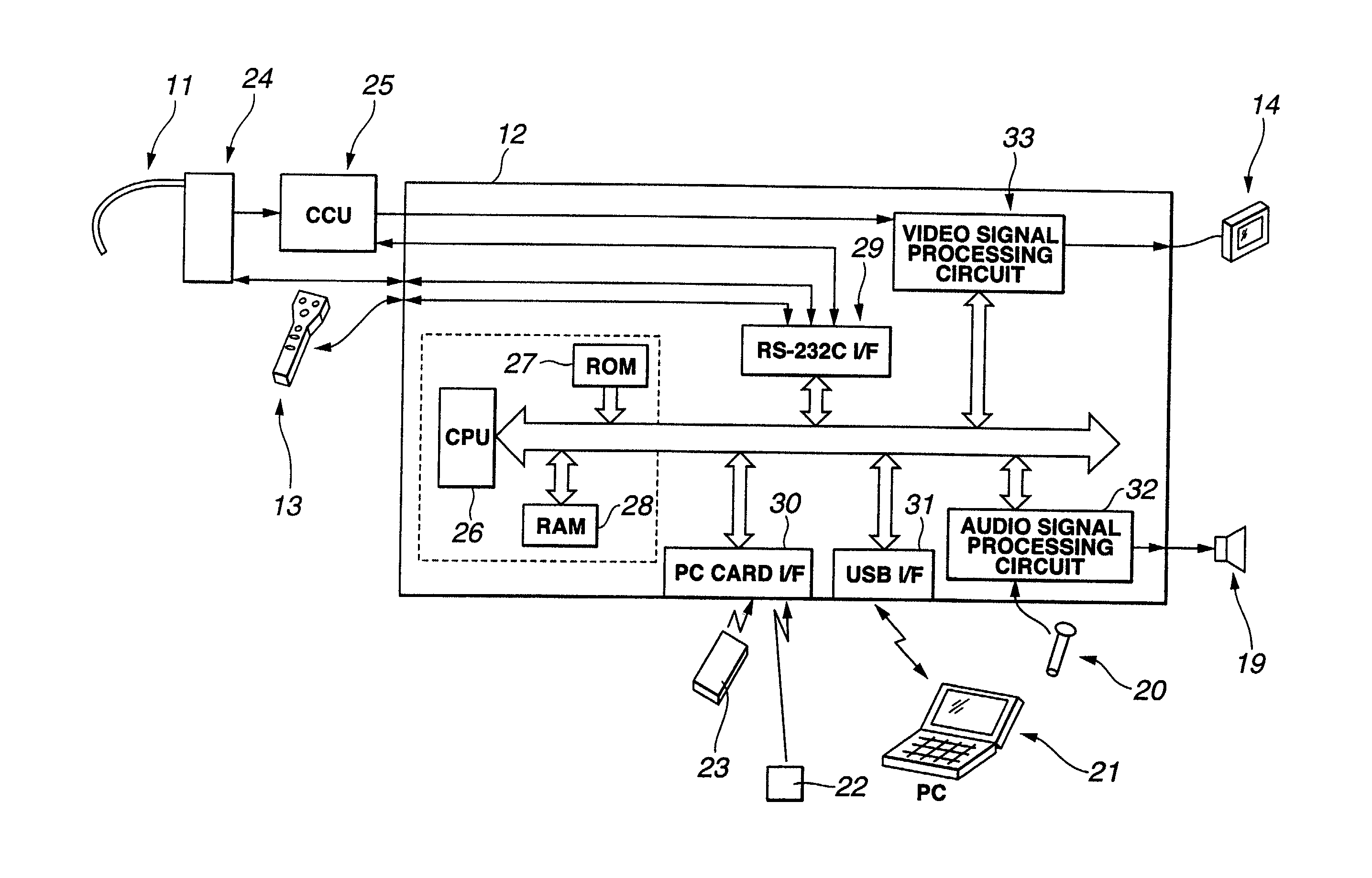
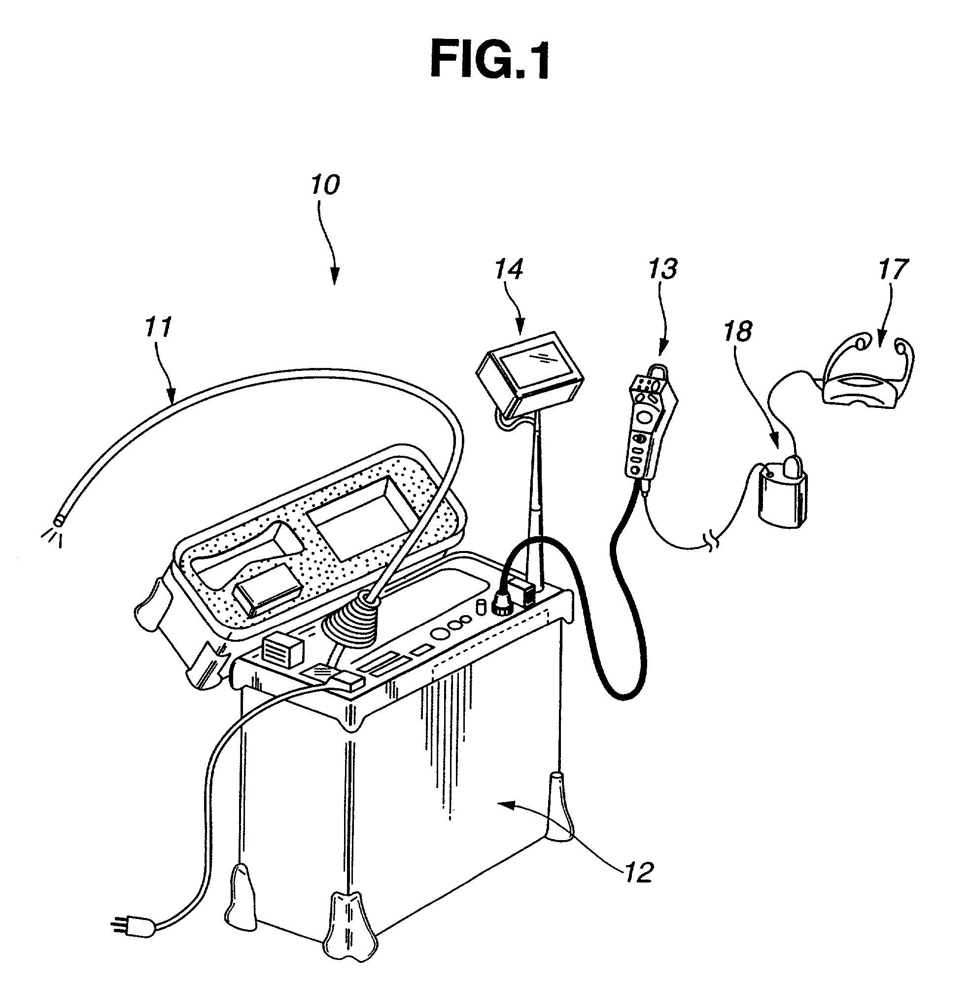
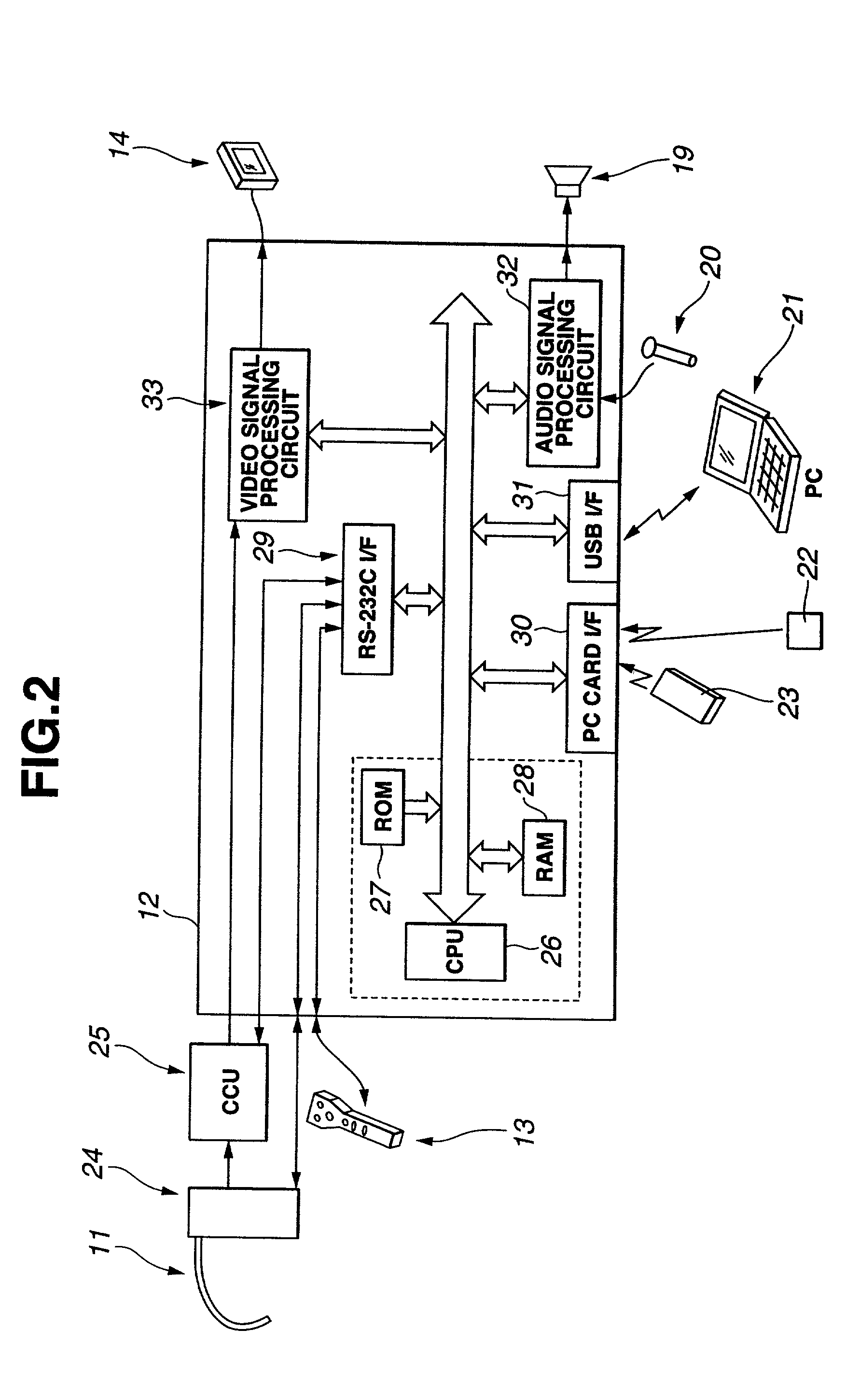
[0046]FIG. 1 to FIG. 16 show a first embodiment of a measuring endoscope system in accordance with the present invention. FIG. 1 is a perspective view showing the configuration of a measuring endoscope system in accordance with the first embodiment of the present invention. FIG. 2 is a block diagram showing the electrical circuitry of the measuring endoscope system shown in FIG. 1. FIG. 3 is a perspective view showing the appearance of an endoscopic distal part having a stereo measurement adaptor attached thereto. FIG. 4 is an A—A sectional view of the endoscopic distal part shown in FIG. 3. FIG. 5 shows an endoscopic image produced by the endoscope system with the stereo measurement adaptor. FIG. 6 is a perspective view showing the appearance of an endoscopic distal part having a normal optical adaptor attached thereto. FIG. 7 is an A—A sectional view of the endoscopic distal part shown in FIG. 6. FIG. 8 shows an endoscopic image produced by the endoscope system w...

second embodiment

(Second Embodiment)

[0118]According to the present embodiment, in efforts to more quickly implement an optimal measuring technique, a program to be run in the measuring endoscope system 10 of the first embodiment has been innovated. The second embodiment is different from the first embodiment in terms of this point.

[0119]To be more specific, in the measuring endoscope system of the second embodiment, a measuring technique is implemented by selecting a menu item from a menu presented by a measuring program under the control of the CPU 26 but not by pressing the measurement execution switch 51.

[0120]In the measuring endoscope system of the second embodiment, a program to be run by the CPU 26 is almost identical to the one described in the flowchart of FIG. 9A and installed in the first embodiment except that the measurement execution routine (except step S110) described in FIG. 9B is run as facility 1 to be activated at step S100.

[0121]The other features are substantially identical to ...


PUM


Abstract

A measuring endoscope system includes a menu display module that selects a menu according to display data which is associated in advance with any of a plurality of optical adaptors, and a measuring program for performing measurement according to the result of the selection performed by the menu display module. Consequently, in the measuring endoscope system, when a user designates an optical adaptor using an optical adaptor selection screen image displayed on an LCD by the menu display module, a measuring technique associated with the optical adaptor is automatically selected. When a user wants to perform measurement using the measuring endoscope system, the user should merely press a measurement execution switch included in an endoscopic operation unit. Thus, measurement in which the selected measuring technique is implemented is carried out. Consequently, the present invention has succeeded in improving the maneuverability of a measuring endoscope system in measurement and improving the efficiency thereof in inspection.

Description

[0001]This application claims the benefit of Japanese Application No. 2000-101122 filed in Japan on Apr. 3, 2000, the contents of which are incorporated by reference.BACKGROUND OF THE INVENTION[0002]1. Field of the Invention[0003]The present invention relates to a measuring endoscope system that images an object to be inspected (object) and then measures the object to be inspected.[0004]2. Description of the Related Art[0005]In general, it is necessary to measure an object to be inspected (object) for the purpose of inspecting the detail of the object to be inspected (object).[0006]When it comes to conventional endoscope systems, a measuring means that enables measurement of an object to be inspected (object) is needed for realization of endoscopic observation.[0007]In order to meet the diverse demands, various proposals have been made of the measuring means for endoscopes, and disclosed in, for example, Japanese Unexamined Patent Application Publications Nos. 10-248806 and 60-23741...

Claims


Application Information

Patent Timeline
Patent Type & Authority Patents(United States)
IPC IPC(8): A61B1/04G01B11/00A61B1/00A61B1/05G01B11/02G01B11/24G01B11/245G01B11/28G01B11/30G02B23/26H04N7/18
CPCA61B1/00048A61B1/05A61B1/00193A61B1/00105
Inventor SAKIYAMA, KATSUNORI
Owner EVIDENT CORP
Why Eureka
Try Eureka