Fractional-integer phase-locked loop system with a fractional-frequency-interval phase frequency detector

a phase-locked loop and fractional-frequency interval technology, which is applied in the field of phase-locked loop (“ pll”) circuits, can solve the problems of increasing the phase noise that is introduced into the pll and increasing the phase nois

Active Publication Date: 2006-05-23
CIRRUS LOGIC INC
View PDF2 Cites 15 Cited by
  • Summary
  • Abstract
  • Description
  • Claims
  • Application Information

AI Technical Summary

Problems solved by technology

However, dynamic switching of the divider module between two integer values increases the phase noise that is introduced into the PLL.
For example, for each reference period, a difference between the actual divider module value and an average ideal value represents an error that is injected into the PLL, which results in increased phase noise.

Method used


Image

  • Fractional-integer phase-locked loop system with a fractional-frequency-interval phase frequency detector
  • Fractional-integer phase-locked loop system with a fractional-frequency-interval phase frequency detector
  • Fractional-integer phase-locked loop system with a fractional-frequency-interval phase frequency detector

Examples


Embodiment Construction

[0019]A fractional-frequency-interval phase frequency detector for a phase locked loop (“PLL”) circuit is disclosed.

[0020]It is well known in the art that signals for a PLL circuit can be either voltage signals or current signals. Conversion between the voltage and current domains can be performed. Therefore, a PLL circuit could be described as a system having either a respective voltage or current mode filter and either a respective voltage or current controlled oscillator.

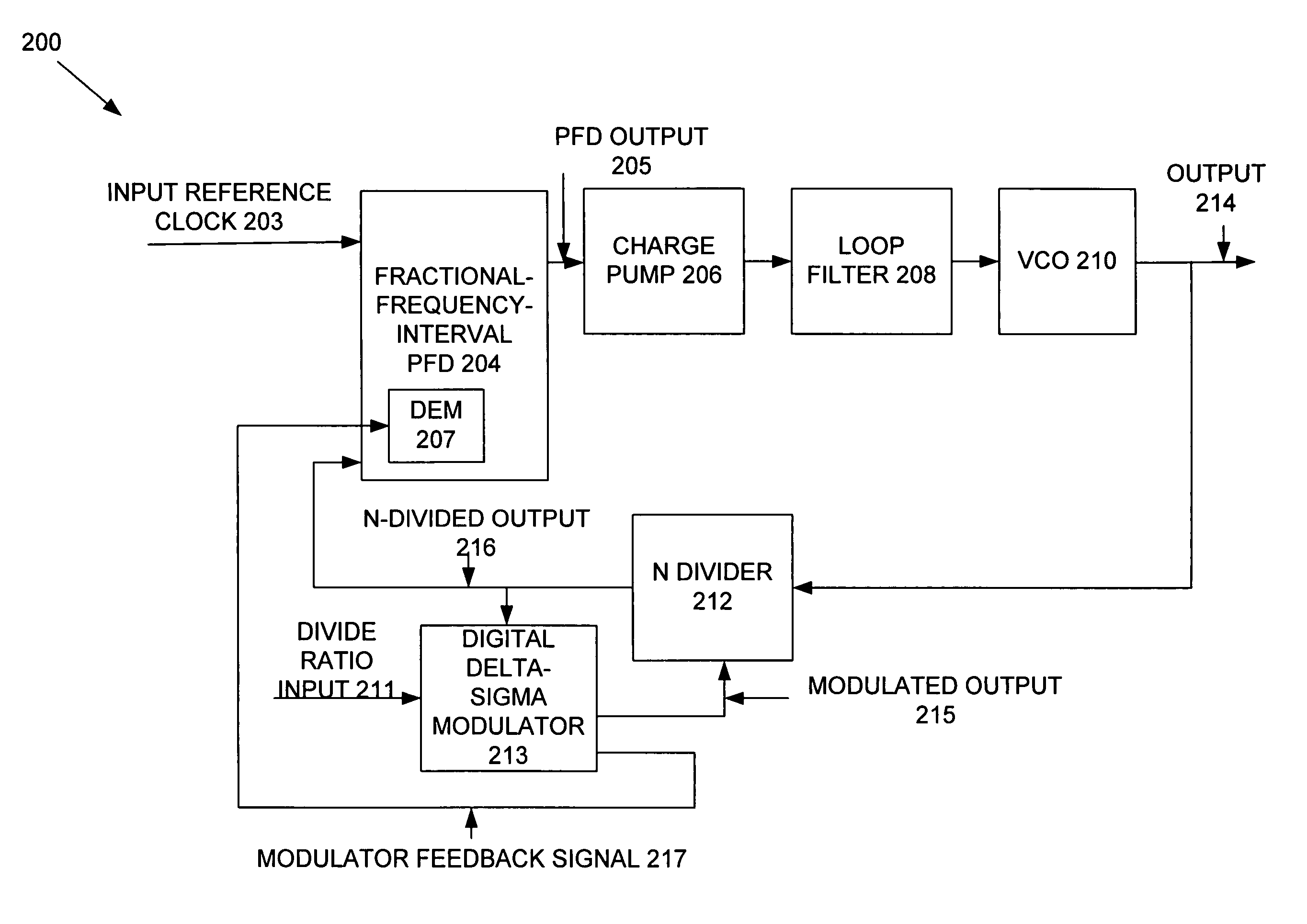
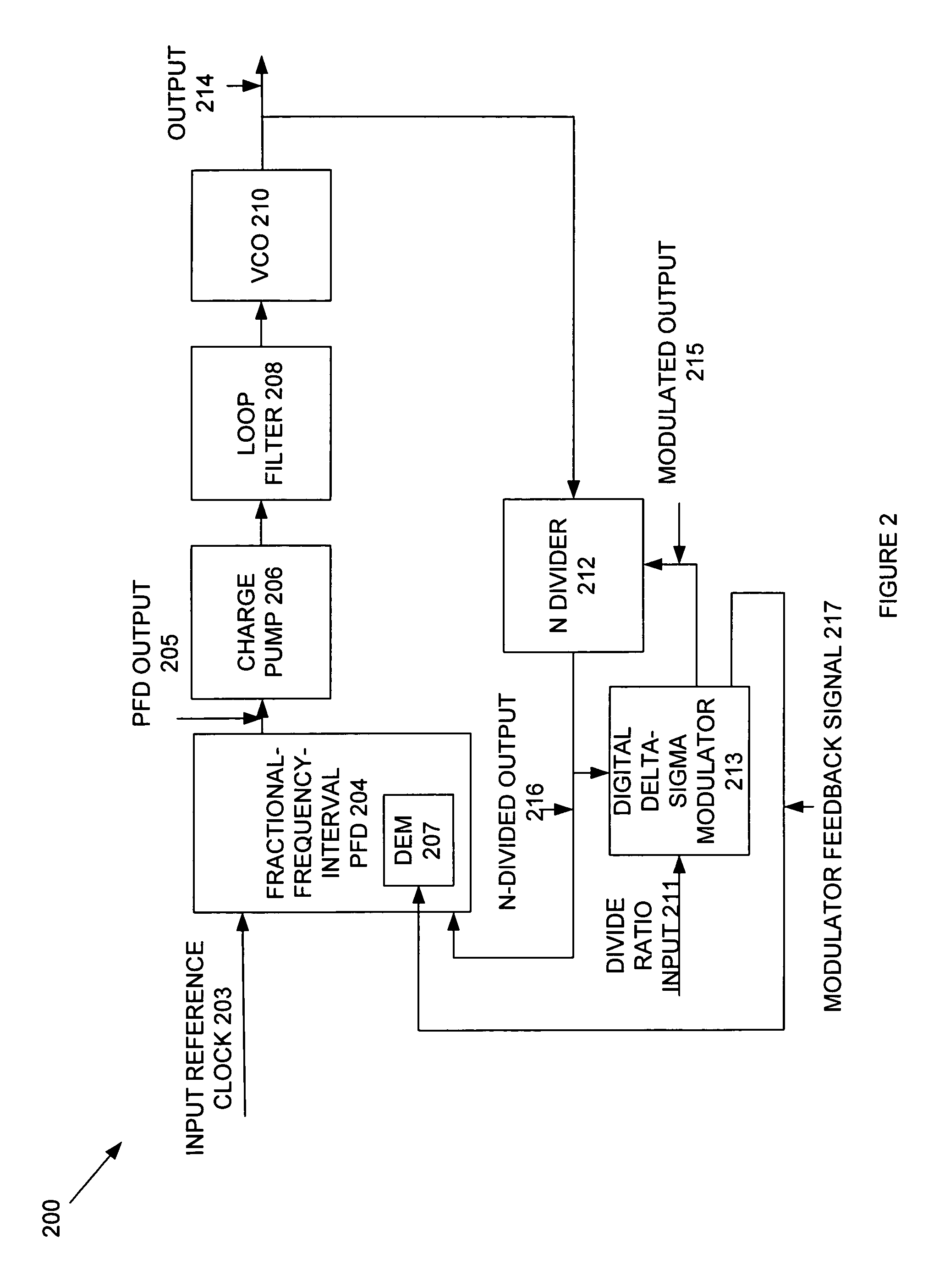
[0021]With reference now to FIG. 2, an exemplary delta-sigma fractional-integer phase-locked loop (“PLL”) circuit 200 according to the present invention is shown. Fractional-integer PLL circuit 200 includes a fractional-frequency-interval phase frequency detector (“PFD”) 204, a charge pump 206, a loop filter system 208, and a voltage controlled oscillator (“VCO”) 210 coupled together in series as shown in FIG. 2. An input reference clock signal 203 is fed into an input node of fractional-frequency-interval PFD 20...


PUM


Abstract

A phase-locked loop circuit has a fractional-frequency-interval phase frequency detector, a charge pump, an oscillator, and a divider. The fractional-frequency-interval phase frequency detector has a phase frequency detector unit that is utilized as or comprises a plurality of phase frequency detector units. The divider is responsive to the oscillator and provides divider values for dividing an oscillator frequency by the divider values to provide a feedback frequency of a feedback loop signal of the phase-locked loop circuit. A reference input frequency is input as a first input into the phase frequency detector unit. The feedback frequency is input and selectively delayed as second inputs into the phase frequency detector unit so that the second inputs are aligned for input according to the reference input frequency and an oscillator frequency is, in effect, responsive to the phase frequency detector units and allowed to be divided by a fractional-integer divider value.

Description

BACKGROUND OF THE INVENTION[0001]1. Field of the Invention[0002]The present invention relates to phase-locked loop (“PLL”) circuits, and, more particularly, to a fractional-integer PLL circuit. More specifically, the present invention relates to a fractional-integer PLL circuit having a fractional-frequency-interval phase frequency detector.[0003]2. Description of Related Art[0004]A phase-locked loop (“PLL”) circuit generally includes a phase detector, a loop filter, and a controlled oscillator. The phase detector receives an input signal, which has a reference frequency. The output signal of the controlled oscillator is fed back to the phase detector. The frequency of the output signal is typically a multiple of the reference frequency of the input signal. The PLL circuit is utilized to lock the output frequency to the input frequency. Locking the output frequency to the input reference frequency is critical in various applications, such as developing accurate and precise clocks fo...

Claims


Application Information

Patent Timeline
Patent Type & Authority Patents(United States)
IPC IPC(8): H03K21/00H03K23/54H03K23/68
CPCH03K23/68H03K23/546
Inventor MELANSON, JOHN L.
Owner CIRRUS LOGIC INC
Why Eureka
Try Eureka