System and method for dynamic allocation of capacity on wireless networks

Inactive Publication Date: 2006-05-23
AT&T INTPROP I L P
View PDF59 Cites 66 Cited by
  • Summary
  • Abstract
  • Description
  • Claims
  • Application Information

AI Technical Summary

Benefits of technology

[0007]The present invention allocates network access for transactions in a wireless network according to the priority levels associated with the transactions. When all access links are occupied on the wireless network, an access control manager in the wireless network discontinues transmission of a low priority transaction in favor of a higher priority transaction. When a transaction is discontinued, the transaction data that was not transmitted is maintained in a data buffer. When the transaction is resumed later, the remaining transaction data is removed from the data buffer. There can be data remaining in the data buffer from several different transactions of different priorities. Requests to resume transactions occur in an order according to the relative priority designated for the different transactions in the data buffer.
[0008]A wireless handset, or a wireless communications device, generates transactions through user applications operating in the handset. The transactions can have a default priority level, or the priority levels can be selected by the user. E-mail and voice-over-IP transactions are discussed, wherein the transaction is periodically discontinued, or suspended, in favor of a higher priority transaction.
[0009]In accordance with the present invention, a wireless communication system is described for allocating limited network access according to priorities designated for requested transactions of wirele

Problems solved by technology

This is known to be inefficient for “bursty” type communications, because the dedicated lines occupy the limited bandwidth in the network for the duration of the communication, even during periods of time when information signals are not being transmitted.
The circuit-switched protocol is also inefficient for voice communications, because there are gaps of silence in most voice communications in which no signal needs to be transmitted.
For wireless communications, a bottleneck occu

Method used


Image

  • System and method for dynamic allocation of capacity on wireless networks
  • System and method for dynamic allocation of capacity on wireless networks
  • System and method for dynamic allocation of capacity on wireless networks

Examples


Example

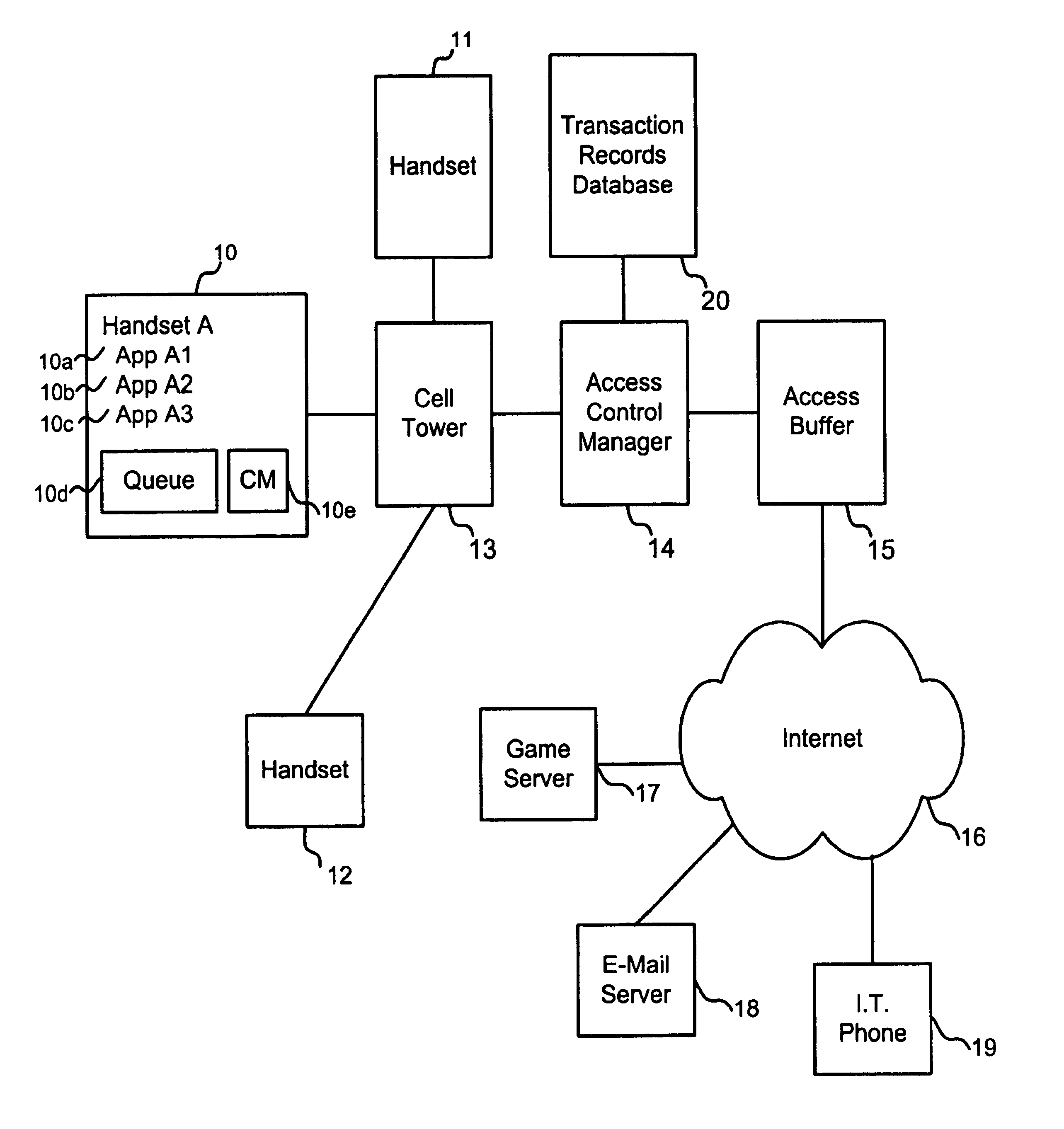
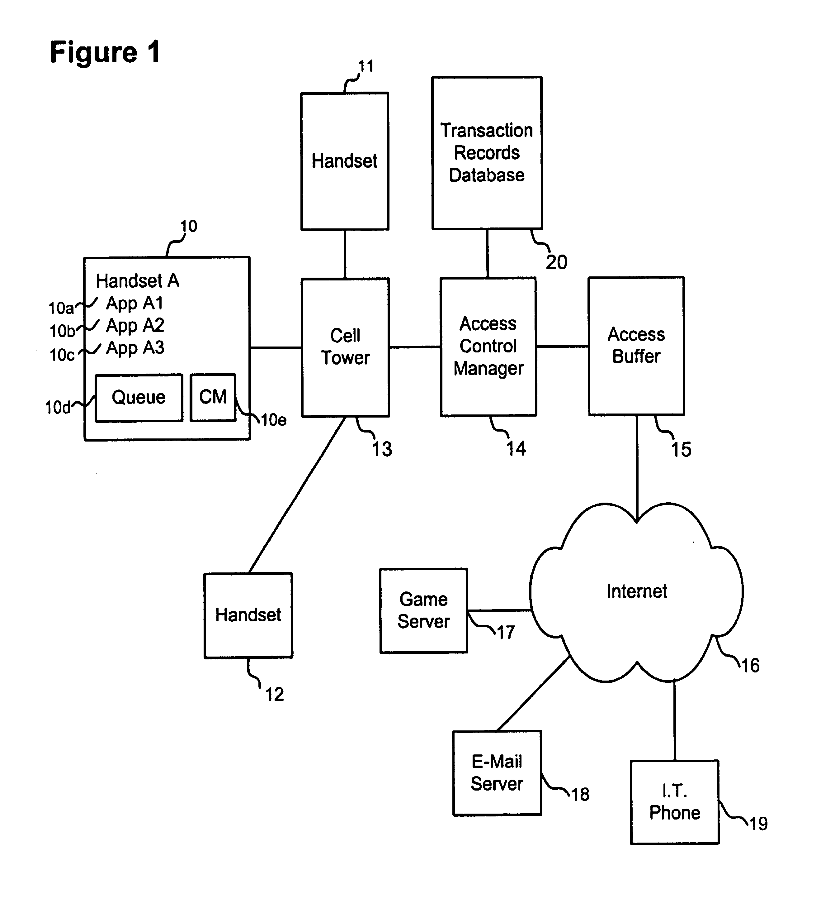
[0021]FIG. 1 is a schematic diagram of the multi-level wireless network service of the present invention. Three mobile transmitter / receiver handsets 10, 11, and 12 are physically located in close proximity to cell tower 13, which is part of a packet switched wireless network. Each handset is capable of supporting at least one or any number of applications, and contains a queue, or buffer, for temporarily storing data packets to be communicated to cell tower 13. A communications manager in the handset stores control information to be transmitted to cell tower 13 to initiate a wireless communication. For example, Handset A 10 is capable of running at least three applications, App. A1, App. A2, and App. A3, labelled 10a-10c, respectively, and contains queue 10d and communications manager 10e. Cell tower 13 transmits and receives radio frequency signals within a general region or cell.

[0022]The handset s may be portable, such as cellular telephones, PDA's, or portable game systems, or a...


PUM


Abstract

A wireless communication system is described for allocating limited network access according to priorities designated for requested transactions of wireless communications. The wireless network has a number of access links for transmitting transactions for wireless communications. A plurality of wireless communications devices request transmission of transactions on the wireless network. A designated priority level is associated with each transaction. In response to the transaction requests, an access control manager in the wireless network schedules transmission of transactions when all of the plurality of access links are occupied, by authorizing a transmission of a transaction of higher priority than another transaction that is being transmitted, and discontinuing the transmission of the transaction of lower priority.

Description

[0001]This application is a continuation-in-part application of Ser. No. 08 / 903,534, now U.S. Pat. No. 6,069,882 filed on Jul. 30, 1997 (the '882 patent). The present application claims priority from the '882 patent which is incorporated herein by reference. The application also incorporates by reference U.S. application Ser. No. 09 / 559,593, filed Apr. 28, 2000.FIELD OF THE INVENTION[0002]The present invention relates to wireless communication services, and more particularly, to a system and method for dynamic allocation of limited capacity on a wireless network.BACKGROUND OF THE INVENTION[0003]Through the combination of wireless telephony and mobile computing technologies, digital wireless handsets are now available that can allow users to communicate with others by voice, e-mail, paging, facsimile, etc., and to transmit or receive information through the internet over a wireless network. Manufacturers of internet-capable telephones and personal digital assistants (PDA's) are coord...

Claims


Application Information

Patent Timeline
IPC IPC(8): H04L12/26G06F11/00G08C15/00H04J1/16H04J3/14H04L1/00H04W72/10H04W72/12H04W76/06
CPCH04L12/5695H04L47/14H04L47/15H04L47/805H04L47/824H04W72/10H04L47/745H04W76/06H04L47/70H04W76/30H04W28/02H04W72/56H04W8/04
Inventor ZELLNER, SAMUEL N.ENZMANN, MARK J.
Owner AT&T INTPROP I L P
Why Eureka
Try Eureka