Process for repairing turbine components

a technology for turbine components and components, which is applied in the direction of engine starters, machines/engines, and machine/engines, etc., can solve the problems of loss of turbine operating efficiency, thermal expansion and thermal expansion wear of exposed parts of turbine components, and cyclic loading of thermal expansion and hot gas flow,

Active Publication Date: 2006-05-30
GENERAL ELECTRIC CO
View PDF26 Cites 58 Cited by
  • Summary
  • Abstract
  • Description
  • Claims
  • Application Information

AI Technical Summary

Benefits of technology

[0009]Disclosed herein is a process for repairing a turbine component, comprising overlaying a preform of a brazing material onto a surface of the turbine component, wherein the surface comprises a damaged

Problems solved by technology

In the turbine section of a gas turbine engine, components are often subjected to significant temperature extremes and contaminants present in combustion gases resulting in cyclic loading from thermal expansion as well as wear from the hot gas flow.
As a result of operating in such an environment, exposed portions of the turbine components are subject to degradation.
These types of degradation can lead to a loss in turbine operating efficiency and possible damage to components located downstream from the degraded portion as a result of separation and contact therewith.
Because welding heat is intense, it is impractical to apply it uniformly over a broad area.
Unfortunately, because of the non-uniform concentrated heating and high temperatures employed, welding processes can cause a significant distortion to the turbine component to be repaired due to the severe thermal gradients acr

Method used


Image

  • Process for repairing turbine components
  • Process for repairing turbine components
  • Process for repairing turbine components

Examples


example 1

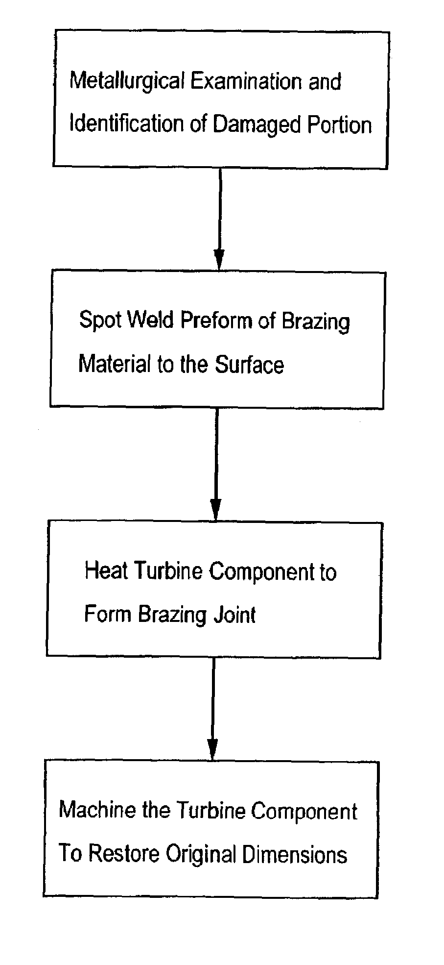
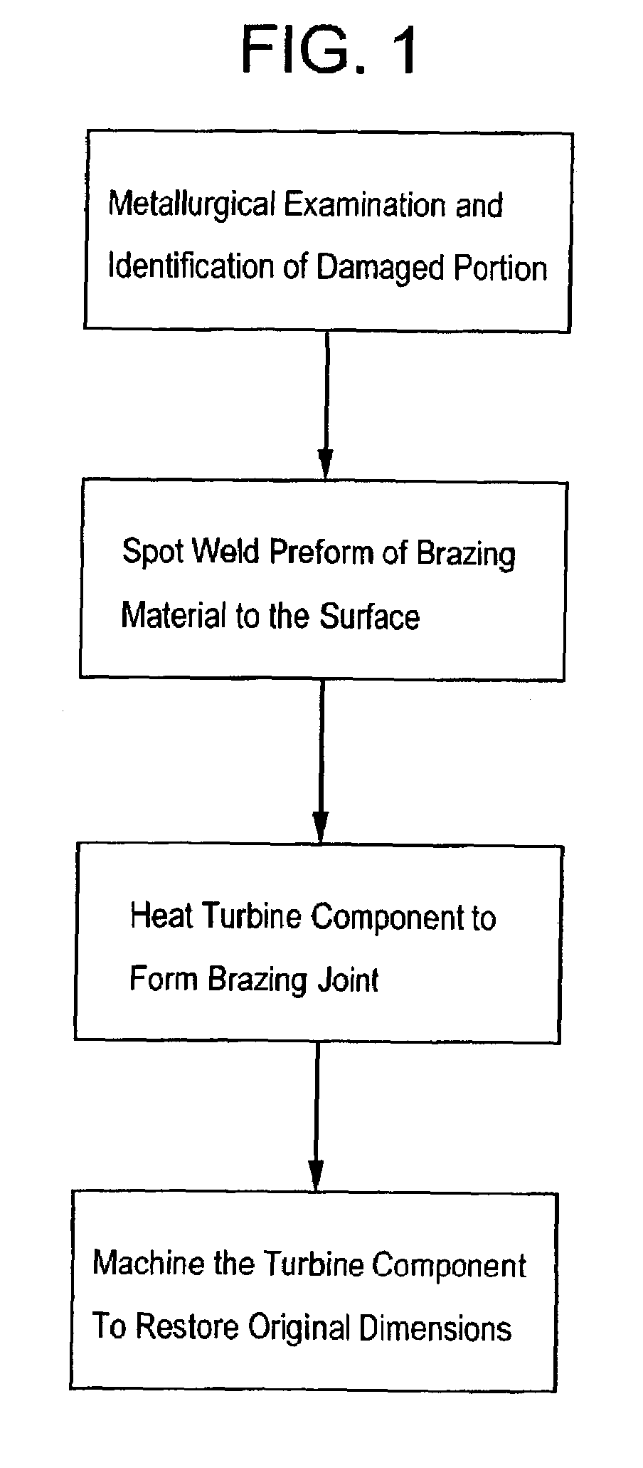
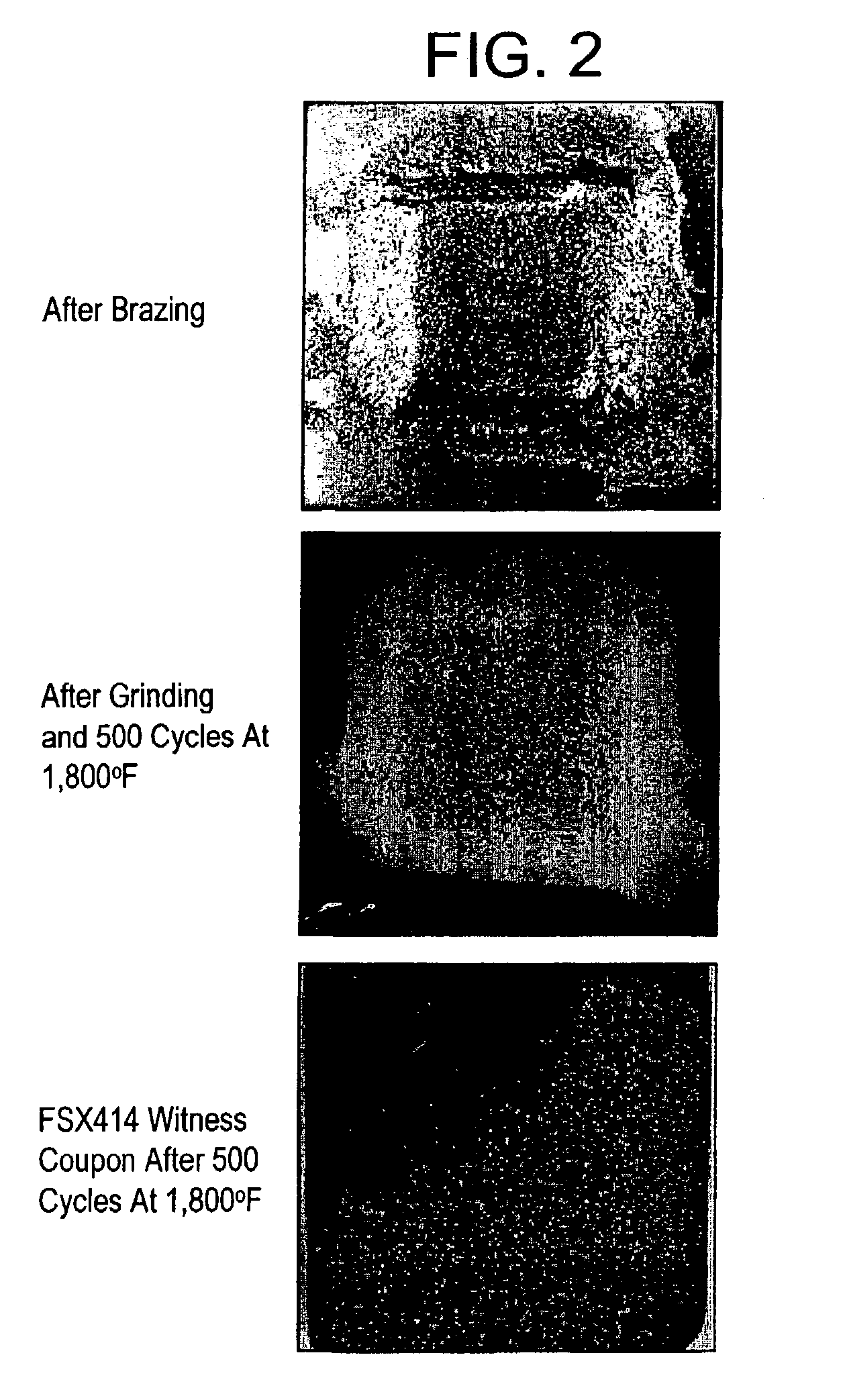
[0029]In this example, presintered preforms of a brazing material and a metal alloy substrate were used to simulate a repair of a turbine component. A 1-inch by 1-inch cavity was milled into an alloy substrate, commercially available under the tradename FSX414 from Howmet Castings. The presintered preform was a commercially available brazing alloy under the tradename X40 / D15 from the Aerospace International Materials, Inc. The brazing alloy was obtained as a preform having the following dimensions: 4 inch by 4 inch by 60 mils. FIG. 1 illustrates the process flow for brazing the preform to the FSX414 substrate. Prior to processing, the FSX414 substrate was exposed to hydrogen gas at 2100° F. for about 2 hours. In addition, a paste was applied to the seams formed between the spot welded preform and the substrate. The substrate and preform were then stepwise heated from about room temperature to about 2100° F. and cooled back to room temperature. The applied braze filler metal past, ob...

example 2

[0030]In this example, a section of a nozzle was removed and subjected to the brazing process as in Example 1. After brazing, the surface was machined to its original dimensions. FIG. 3 illustrates a plan view of the nozzle section, with the location of the replaced section identified. The micrographs clearly show that the openings are substantially unaffected by the brazing process.

example 3

[0031]In this example, tensile strength was measured at room temperature and at 1,500° F. The test structure dimensions are shown in FIG. 4. FSX414 alloy was employed as the base metal. The brazing alloy was the X40 / D15 alloy. The brazed joint was formed as defined by the brazing process of Example 1. A comparison of the test structure with and without the brazed joint (the parent component by itself and configured in the shape as dimensioned for the test structure) was made. Tensile strength measurements were made on an Instron Model No. 1125 screw driven frame at 0.02 inches per minute. The results are shown in Table 1, which clearly show that tensile strength, yield stress, and percent elongation for the brazed material was about same or stronger than the parent material by itself. The results demonstrate that brazed joint provided structural soundness to the structure equivalent or better than the parent structure.

[0032]

TABLE 1Temperature0.2% YieldUltimate TensileElongation toMa...


PUM

PropertyMeasurementUnit
Temperatureaaaaaaaaaa
Melting pointaaaaaaaaaa

Abstract

A process for repairing a turbine component comprises overlaying a preform of a brazing material onto a surface of the turbine component, wherein the surface comprises a damaged portion; securing the preform of a brazing material to the surface; and heating the turbine component to a temperature effective to form a brazed joint between the brazing material and the turbine component. Also disclosed is a repaired turbine component repaired by the process.

Description

BACKGROUND[0001]This disclosure relates to a process for repairing damaged portions of a metal component and to a repaired metal component. More particularly, it relates to a process for repairing turbine components and to repaired turbine components.[0002]Certain components of a power generating apparatus, for example a turbine engine, operate in a hot gas path of the apparatus. In the turbine section of a gas turbine engine, components are often subjected to significant temperature extremes and contaminants present in combustion gases resulting in cyclic loading from thermal expansion as well as wear from the hot gas flow. As a result of operating in such an environment, exposed portions of the turbine components are subject to degradation. Various forms of degradation may include, but are not limited to, oxidation effects, crack formation, and / or erosion and wear, such as on the airfoil and sidewall surfaces of the turbine component. These types of degradation can lead to a loss ...

Claims


Application Information

Patent Timeline
IPC IPC(8): B23P6/00F01D25/00B23K1/00B23K1/008B23K1/19B23K1/20B23K11/00B23K31/00B23K31/02F01D19/02F01D25/28F02C7/00
CPCB23K1/0018B23K1/008B23K1/19B23K1/20B23K11/0033B23P6/005Y10T29/49318Y10T29/49336Y10T29/49734Y10T29/49737B23K2201/001B23K2101/001B23K1/00F01D19/02F01D25/28
Inventor SUBRAMANIAN, PAZHAYANNUR RAMANATHANRUUD, JAMES ANTHONYCRETEGNY, LAURENT
Owner GENERAL ELECTRIC CO
Why Eureka
Try Eureka