Facet joint prosthesis measurement and implant tools

a facet joint and prosthesis technology, applied in the field of facet joint prosthesis measurement and implant tools, can solve the problems of severe limitations on a person's functional ability and quality of life, damage to the facets of one or more vertebrae, and the inability to properly align the vertebrae,

Active Publication Date: 2006-05-30
GLOBUS MEDICAL INC
View PDF155 Cites 252 Cited by
  • Summary
  • Abstract
  • Description
  • Claims
  • Application Information

AI Technical Summary

Benefits of technology

[0019]In order to accommodate such variations in anatomy, a configurable and / or modular prosthesis system (comprising multiple configurable and / or interchangeable components of varying shapes and / or sizes) may be used to tailor the prosthesis to the varying anatomical demands of a given patient. Once the surgical site has been prepared, the prosthesis can be assembled and / or configured from components chosen by the physician based on anatomical measurements of the treatment site during the surgery. The disclosed invention desirably facilitates such measurements of the treated anatomy.
[0023]The fixation measurement element in one embodiment is adapted and configured to permit measurements for determination of the length of the fixation element of a cephalad facet joint prosthesis for implantation in a patient. In another embodiment, the fixation measurement element includes markings to assist in the determination of the length of the fixation element of a cephalad facet joint prosthesis.
[0024]In another aspect, the present invention provides a caudal facet joint prosthesis measurement system including a stem element and a trial caudal bearing surface element connected to each other by a fastener or fastening mechanism. This measurement tool assists in the selection of a caudal facet joint prosthesis for implantation in a patient. The measurement tool can be used in the determination of the dimensions of a caudal facet joint prosthesis. Particularly, this measurement tool can be used to determine the length of the fixation element of the caudal facet joint prosthesis to be implanted in a patient. Also, this tool can be used to determine the angle between the artificial facet joint element and fixation element of the caudal facet joint prosthesis. If desired, the mechanism can permit motion between the elements for alignment purposes and also allow locking of the chosen configuration / orientation once determined.
[0028]In one aspect, the invention is a measurement tool holder including a measurement surface connected to a holder element. This tool holder assists in determining the angle measurements obtained with the caudal facet joint prosthesis measurement tool. The caudal facet joint prosthesis measurement tool can be placed in the tool holder and the angle between the artificial facet joint element and fixation element of a caudal facet joint prosthesis can be determined.

Problems solved by technology

In many cases, the pain severely limits a person's functional ability and quality of life.
Through disease or injury, the laminae, spinous process, articular processes, or facets of one or more vertebral bodies can become damaged, such that the vertebrae no longer articulate or properly align with each other.
This can result in an undesired anatomy, loss of mobility, and pain or discomfort.
For example, the vertebral facet joints can be damaged by either traumatic injury or by various disease processes.
The damage to the facet joints often results in pressure on nerves, also called “pinched” nerves, or nerve compression or impingement.
The result is pain, misaligned anatomy, and a corresponding loss of mobility.
These traditional treatments are subject to a variety of limitations and varying success rates.
None of the described treatments, however, puts the spine in proper alignment or returns the spine to a desired anatomy.
In addition, stabilization techniques, by holding the vertebrae in a fixed position, permanently limit a person's mobility.

Method used


Image

  • Facet joint prosthesis measurement and implant tools
  • Facet joint prosthesis measurement and implant tools
  • Facet joint prosthesis measurement and implant tools

Examples


Embodiment Construction

[0042]Although the disclosure presented herein provides details to enable those skilled in the art to practice various embodiments of the invention, the physical embodiments disclosed herein merely exemplify the invention which may be embodied in other specific structures. Accordingly, while preferred embodiments of the invention are described below, details of the preferred embodiments may be altered without departing from the invention. All embodiments that fall within the meaning and scope of the appended claims, and equivalents thereto, are intended to be embraced by the claims.

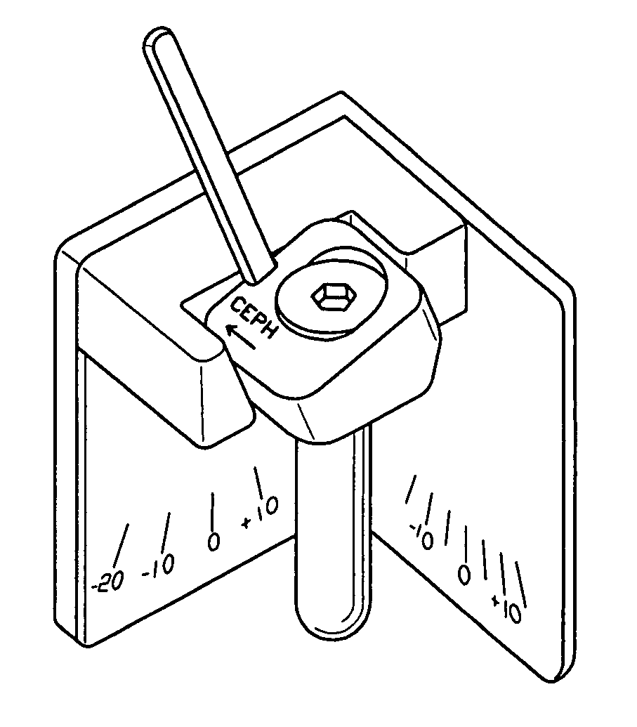
[0043]FIGS. 5 and 6 depict one embodiment of a measurement tool for installing a cephalad facet joint prosthesis. The measurement tool can be used to assist in the installation of cephalad facet joint prostheses such as those described in U.S. patent application Ser. No. 10 / 737,705 or other cephalad facet joint prostheses.

[0044]For purposes of illustrating the invention, one example of a cephalad facet jo...


PUM


Abstract

The present invention provides tools and methods designed to aid in the placement of facet joint prosthesis at virtually all spinal levels. One aspect of the present invention is a measurement tool for installing a cephalad facet joint prosthesis including a fixation measurement element and a support arm element. This measurement tool assists in the selection and / or configuration of a cephalad facet joint prosthesis for implantation in a patient. Another aspect is a measurement tool for installing a caudal facet joint prosthesis including a stem element and a trial caudal bearing surface element. This measurement tool assists in the selection and / or configuration of a caudal facet joint prosthesis for implantation in a patient. Yet another aspect is a measurement tool holder including a measurement surface connected to a holder element. This tool holder assists in determining the measurements obtained with the caudal facet joint prosthesis measurement tool.

Description

FIELD OF THE INVENTION[0001]This invention relates to prostheses, systems, and methods for treating various types of spinal pathologies, and in particular relates to the sizing and attachment of prostheses to spinal vertebrae.BACKGROUND OF THE INVENTION[0002]The human spinal column 10, as shown in FIG. 1, is comprised of a series of thirty-three stacked vertebrae 12 divided into five regions. The cervical region includes seven vertebrae, known as C1–C7. The thoracic region includes twelve vertebrae, known as T1–T12. The lumbar region contains five vertebrae, known as L1–L5. The sacral region is comprised of five vertebrae, known as S1–S5, while the coccygeal region contains four vertebrae, known as Co1–Co4.[0003]FIG. 2 depicts a superior plan view of a normal human lumbar vertebra 12. Although human lumbar vertebrae vary somewhat according to location, they share many common features. Each vertebra 12 includes a vertebral body 14. Two short bones, the pedicles 16, extend backward fr...

Claims


Application Information

Patent Timeline
Patent Type & Authority Patents(United States)
IPC IPC(8): G01B5/24A61B17/56A61F2/00A61F2/30A61F2/44A61F2/46
CPCA61F2/4657A61F2/4684A61F2/4405A61B17/7001A61F2250/0098A61F2/4611A61F2002/3008A61F2002/30616A61F2002/30617A61F2002/30713A61F2002/3085A61F2002/4658A61F2002/4659A61F2002/4662A61F2002/4668A61F2250/0087A61F2250/0097A61F2002/3071
Inventor AUGOSTINO, TEENA M.BROMAN, RICHARD J.TOKISH, JR., LEONARD
Owner GLOBUS MEDICAL INC
Why Eureka
Try Eureka