Venturi device

a technology of venturi and cylinder head, which is applied in the direction of combustion engines, machines/engines, mechanical equipment, etc., can solve the problem that the effect of ejector cannot be reduced, and achieve the effect of increasing the performance and efficiency of the engine of the vehicl

Inactive Publication Date: 2006-05-30
KRAFT BERNARD A
View PDF17 Cites 34 Cited by
  • Summary
  • Abstract
  • Description
  • Claims
  • Application Information

AI Technical Summary

Benefits of technology

[0021]The present invention discloses a venturi that is installed perpendicularly to the end of the exhaust pipe of a truck or like vehicle thus resulting in the air flow through the venturi being at a 90 degree angle relative to the exhaust gases exiting the exhaust pipe. The present invention seeks to increase the performance and efficiency of an engine of a vehicle by overcoming the backpressure in the engine exhaust system created by the muffler baffles. The present invention may also be installed on automobiles and other motor vehicles having appropriately modified exhaust systems. A front aperture for air intake tapers in width to the back pressure relief port or nozzle being a size slightly greater than the exhaust port on the bottom portion thereof and then widens to form an air discharge port on the rear portion thereof that is substantially wider and longer than the air intake port thereby creating an air pressure differential wherein the reduced pressure in the back pressure relief port serves to create a vortex to draw exhaust gases from the exhaust pipe to the rear discharge port.
[0022]A primary object of the present invention is to provide a device that will reduce backpressure in the exhaust system of diesel engines in trucks.
[0023]Another object of the present invention is to provide an improved venturi that will create a vacuum to evacuate exhaust from the exhaust pipe in a more effective manner.

Problems solved by technology

Therefore, the ejector effect cannot be reduced by the sound suppressing section which is subject to high flow resistance.

Method used


Image

  • Venturi device
  • Venturi device
  • Venturi device

Examples


Embodiment Construction

[0059]The following discussion describes in detail one embodiment of the invention. This discussion should not be construed, however, as limiting the invention to those particular embodiments since practitioners skilled in the art will recognize numerous other embodiments as well. For a definition of the complete scope of the invention, the reader is directed to the appended claims.

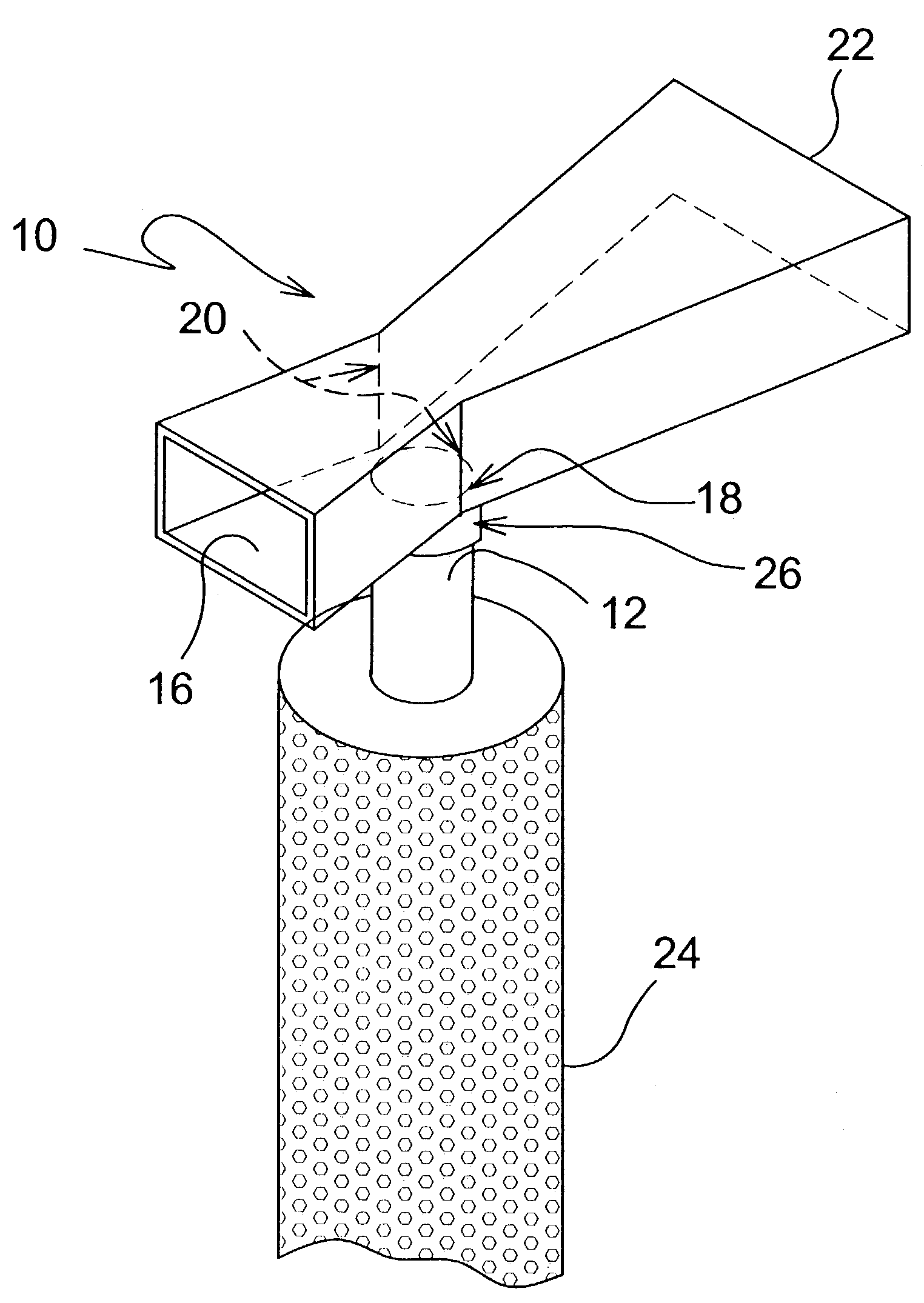
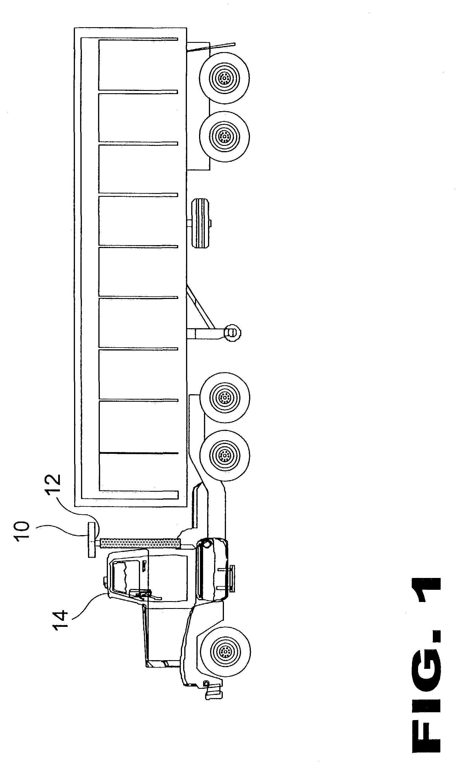
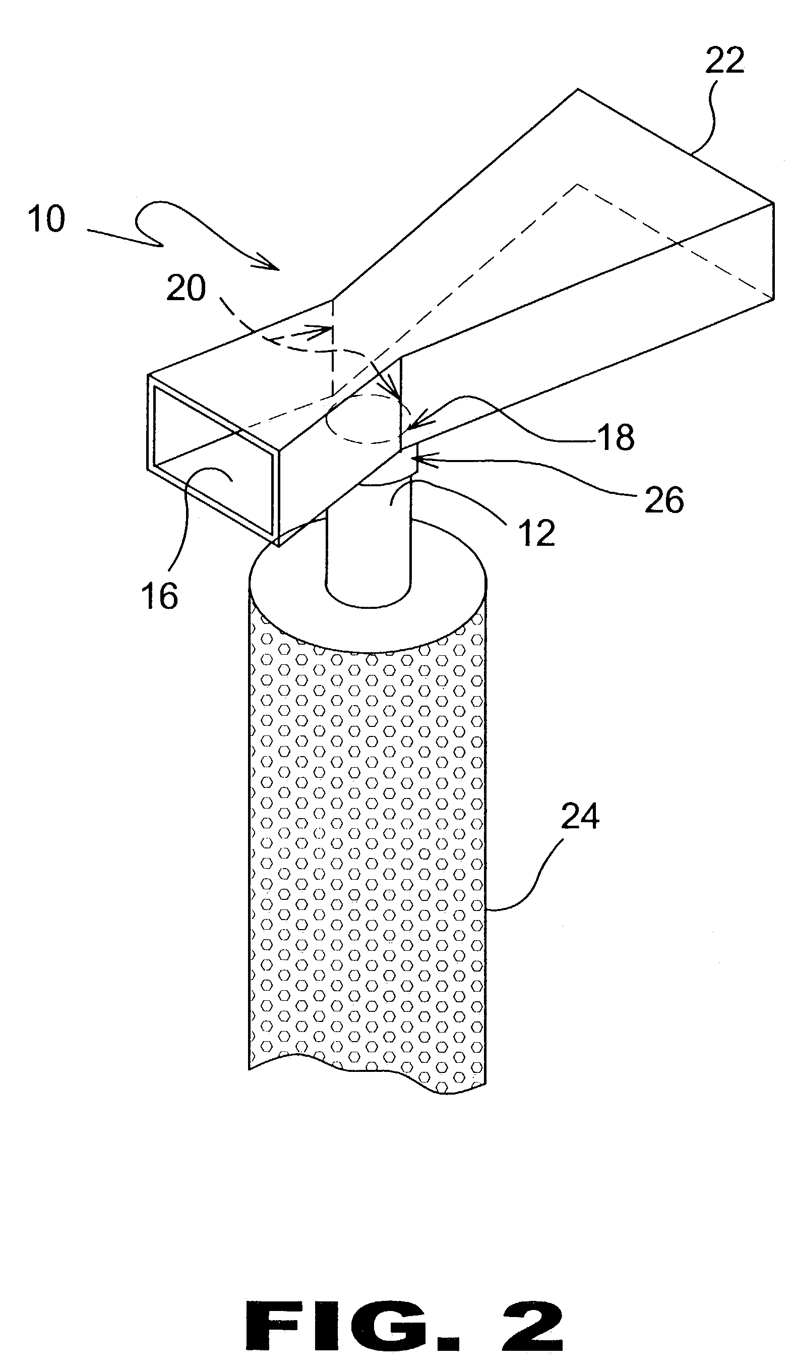
[0060]Turning to FIG. 1, shown therein is a side view of the present invention 10 in use. The present invention 10 discloses a venturi that is installed perpendicularly to the end of the exhaust pipe 12 of a truck or like vehicle 14 thus resulting in the air flow through the venturi being at a 90 degree angle relative to the exhaust gases exiting the exhaust pipe. The present invention 10 seeks to increase the performance and efficiency of an engine of a vehicle 14 by overcoming the backpressure in the engine exhaust system created by the muffler baffles. The present invention 10 may also be installed on ...


PUM


Abstract

The present invention 10 discloses a venturi that is installed perpendicularly to the end of the exhaust pipe 12 of a truck or like vehicle 14 thus resulting in the air flow through the venturi being at a 90 degree angle relative to the exhaust gases exiting the exhaust pipe. The present invention 10 seeks to increase the performance and efficiency of an engine of a vehicle 14 by overcoming the backpressure in the engine exhaust system created by the muffler baffles. The present invention 10 may also be installed on automobiles and other motor vehicles 14 having appropriately modified exhaust systems. A front aperture 16 for air intake tapers in width to the back pressure relief port or nozzle 20 being slightly greater than the exhaust port 18 on the bottom portion thereof and then widens to form an air discharge port 22 on the rear portion thereof that is substantially wider and longer than the air intake port 16 thereby creating an air pressure differential wherein the reduced pressure in the back pressure relief port 20 serves to create a vortex to draw exhaust gases from the exhaust pipe 12 toward the discharge port 22.

Description

BACKGROUND OF THE INVENTION[0001]1. Field of the Invention[0002]The present invention relates generally to venturi devices and, more specifically, to an improved venturi having a front aperture for air intake which tapers in width to a size roughly equivalent to an exhaust intake port on the bottom portion thereof and then widens to form an air discharge port on the rear portion thereof that is substantially wider and longer than the air intake port thereby creating an air pressure differential wherein the reduced pressure in the exhaust port serves to create a vortex to draw exhaust gases from the exhaust pipe to achieve equilibrium.[0003]2. Description of the Prior Art[0004]There are other venturi devices designed for improving exhaust efficiency. Typical of these is U.S. Pat. No. 1,560,947 issued to D. M. Skelton on Nov. 10, 1925.[0005]Another patent was issued to N. G. Warth on Mar. 23, 1926 as U.S. Pat. No. 1,577,626. Yet another U.S. Pat. No. 1,638,087 was issued to V. E. Clar...

Claims


Application Information

Patent Timeline
Patent Type & Authority Patents(United States)
IPC IPC(8): F01N7/00F01N13/08
CPCF01N13/082
Inventor KRAFT, BERNARD A
Owner KRAFT BERNARD A
Why Eureka
Try Eureka