
Bioaerosol slit impaction sampling device

a sampling device and bioaerosol technology, applied in the direction of withdrawing sample devices, material analysis, instruments, etc., can solve the problems of time-consuming filter sampling, limited reliability, and inability to ensure the desired accurate particle accumulation, and samplers typically cannot be used in an upright or fixed position

Inactive Publication Date: 2006-05-30
ENVIRONMENTAL MONITORING SYST
View PDF8 Cites 21 Cited by
  • Summary
  • Abstract
  • Description
  • Claims
  • Application Information

AI Technical Summary

Benefits of technology

[0008]It is therefore an object of the present invention to provide a slit impaction sampling device that allows for the complete collection of a variety of airborne particulates for subsequent analysis.
[0009]It is a further object of the present invention to provide a slit impaction sampling device that creates a laminar flow for a more defined impaction trace, which allows for a more precise analysis.
[0010]It is still another object of the present invention to provide a slit impaction sampling device that allows for inline calibration during operation to account for pressure drops.
[0011]It is yet another object of the present invention to provide a slit impaction sampling device that is reusable.

Problems solved by technology

While effective for some purposes, filter sampling is time consuming and provides only limited reliability.
However, the configuration of these designs does not always ensure the desired accurate particle accumulation.
Moreover, these samplers typically can only be used in an upright or fixed position and cannot be easily used in confined or restricted spaces because of their relatively large size.
This sampler, however, requires the usage of a new sampling cell for each sampling run, thereby making it relatively expensive.
Additionally, the disclosed sampler suffers from some disadvantages in airflow into the sampler that can lead to an incomplete gathering of air particles and therefore affect any conclusions drawn from an analysis thereof.

Method used


Image

  • Bioaerosol slit impaction sampling device
  • Bioaerosol slit impaction sampling device
  • Bioaerosol slit impaction sampling device

Examples


Embodiment Construction

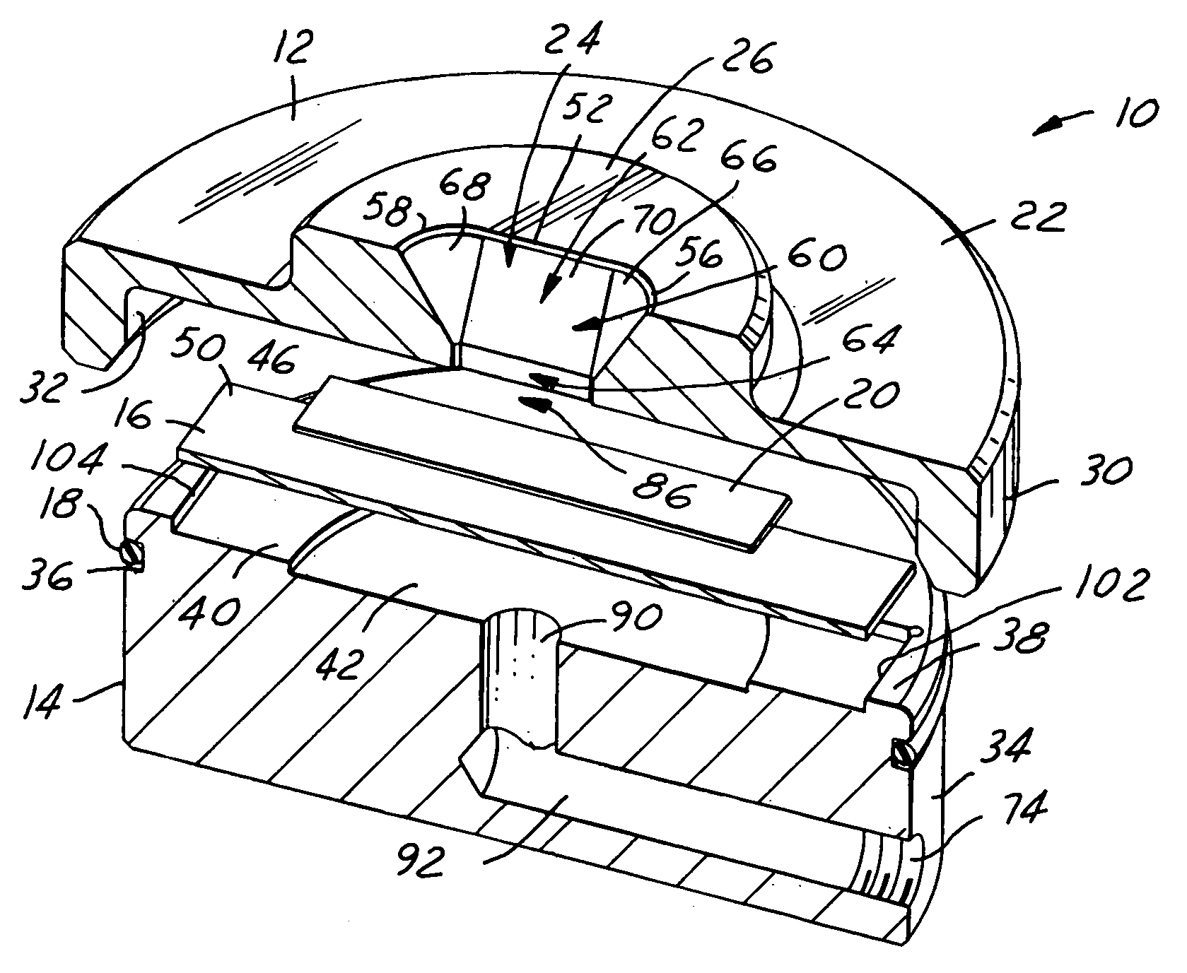
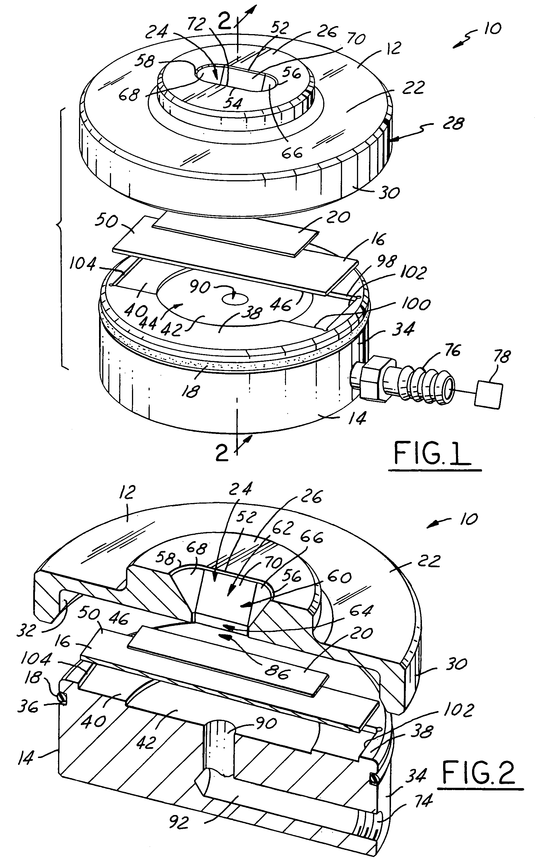
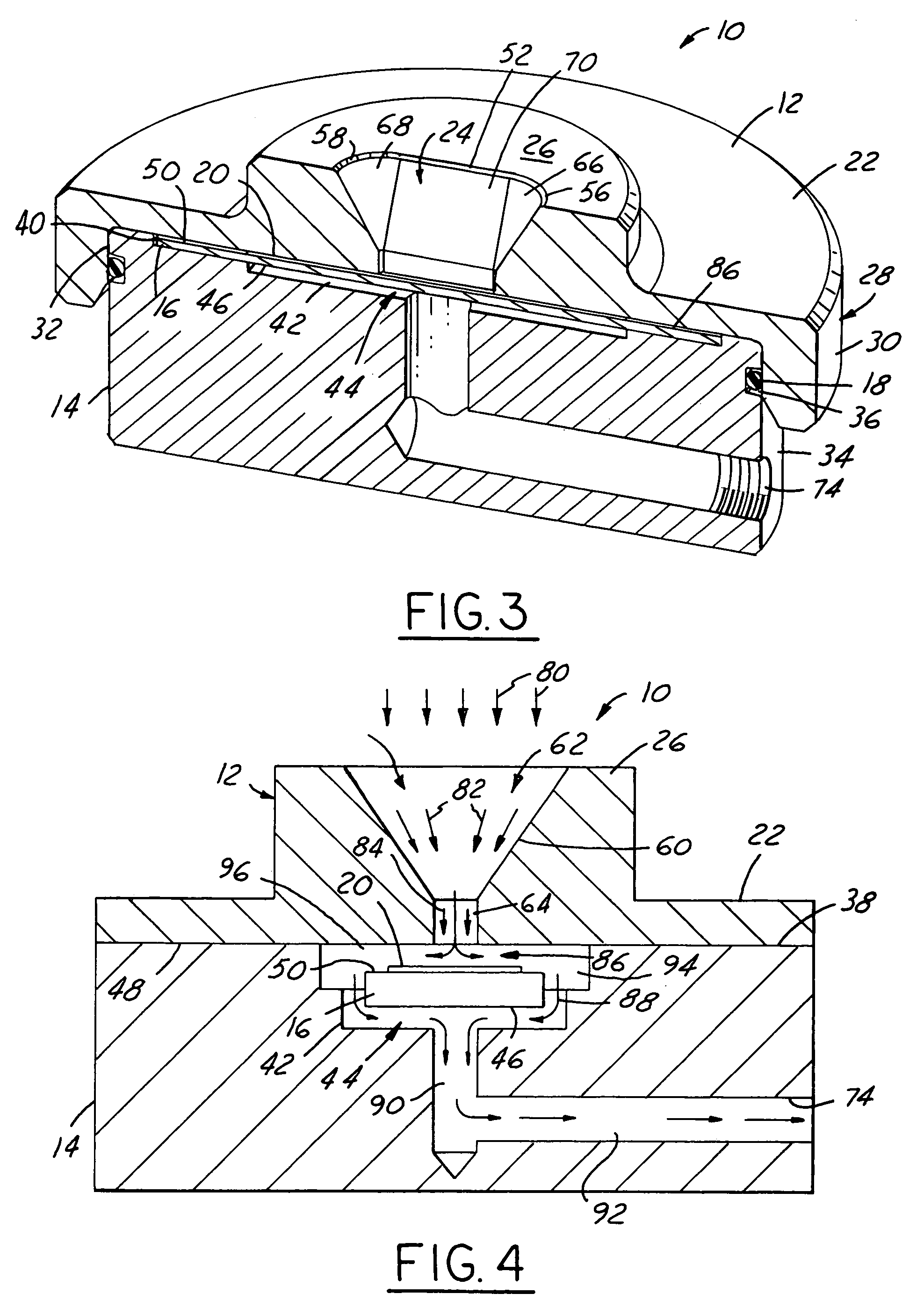
[0018]Referring now to the figures which illustrate a slit impaction sampling device 10 in accordance with the present invention. The sampling device 10 is suitable for the collection of airborne particles, such as mold spores, pollen, skin fragments, insect parts, various fibers, and other aeroallergens for reliable contamination studies and other analysis. The disclosed sampling device 10 may, however, be used for a variety of purposes, in a variety of locations, and for a variety of different applications. The terms “top,”“bottom,”“upper,” and “lower” and other directional terms are used herein to describe the sampling device 10 with respect to the drawings. These terms are not to be construed as limiting the invention to the orientations shown and described. Further, the term slit impaction device or sampler, refers to a device that allows incoming air to be impacted upon a surface leaving a narrow and recognizable impaction trace which can then be removed for analysis.

[0019]As ...


PUM

PropertyMeasurementUnit
vacuumaaaaaaaaaa
depthaaaaaaaaaa
dimensionaaaaaaaaaa

Abstract

A slit impaction sampling device is for collecting airborne contaminants for subsequent analysis, includes a base with a microscope slide disposed thereon. The microscopic slide has an adhesive media located thereon to assist in adhering airborne particles on the microscopic slide. The base has a top cap secured thereto. The top cap has an inlet opening formed therethrough. The inlet opening has an outer venturi section and an inner laminar section that directs the air flow through the inlet opening into contact with the adhesive media such that the airborne particles form an impaction trace thereon. The air then flows around the microscope slide into an outlet passage and to a vacuum source.

Description

CROSS-REFERENCE TO RELATED APPLICATIONS[0001]The present application is a continuation of U.S. application Ser. No. 09 / 705,602, filed Nov. 3, 2000, and entitled “BIOAEROSOL SLIT IMPACTION SAMPLING DEVICE, which is now U.S. Pat. No. 6,463,814.[0002]The present application claims priority from applicant's co-pending provisional application, Ser. No. 60 / 163,872, filed Nov. 5, 1999 and entitled “Slit-Air Sampler.”TECHNICAL FIELD[0003]The present invention relates generally to a method and apparatus for collecting airborne particles, and more specifically to a slit impaction air sampler that allows for more precise analysis of collected airborne particles.BACKGROUND OF THE INVENTION[0004]Obtaining accurate samples of airborne particles such as mold spores, pollen, skin fragments, insect parts, various fibers, and other aeroallergens is necessary or desirable for a number of different purposes, including reliable contamination studies. For example, environmental professionals need accurat...

Claims


Application Information

Patent Timeline
Patent Type & Authority Patents(United States)
IPC IPC(8): G01N1/22G01N1/24G01N1/28G01N15/00G01N15/02
CPCG01N1/2208G01N15/00G01N1/24G01N2015/0261G01N2001/2833G01N2015/0046G01N2001/2223
Inventor LAGRAFF, PAUL L.LETARTE, ROBERT T.
Owner ENVIRONMENTAL MONITORING SYST
Learn More