Method for producing a shaft and device containing one such a shaft

a technology of a shaft and a production method, which is applied in the direction of hoisting equipment, gearing, other domestic articles, etc., can solve the problems of no longer being able to brace the end of the armature shaft, complicated and expensive process of pressing the completed worm onto the armature shaft, etc., to achieve safe and reliable adjusting operation, reduce the cost of production, and achieve the effect of avoiding damage to the teeth

Inactive Publication Date: 2006-05-30
ROBERT BOSCH GMBH
View PDF15 Cites 8 Cited by
  • Summary
  • Abstract
  • Description
  • Claims
  • Application Information

AI Technical Summary

Benefits of technology

[0003]The method of the invention [having the characteristics of claim 1] has the advantage that regardless of the production process for the worm, a bearing surface for supporting the armature shaft can be created in a very simple way. By means of cold forming, and by not using metal-cutting machining, it is possible to produce a bearing point produced economically. The transition zone from the completed worm to the bearing can be kept quite short, and the meshing of teeth is moved close to the bearing point. This makes safe and reliable adjusting operation possible, in which damage to the teeth is effectively avoided.

Problems solved by technology

From a production standpoint, pressing the completed worm onto the armature shaft is a very complicated and expensive process.
As a result, especially in applications in which there is little installation space available, the end of the armature shaft can no longer be braced, or else complicated production processes are required to achieve such a support.

Method used


Image

  • Method for producing a shaft and device containing one such a shaft
  • Method for producing a shaft and device containing one such a shaft
  • Method for producing a shaft and device containing one such a shaft

Examples


Embodiment Construction

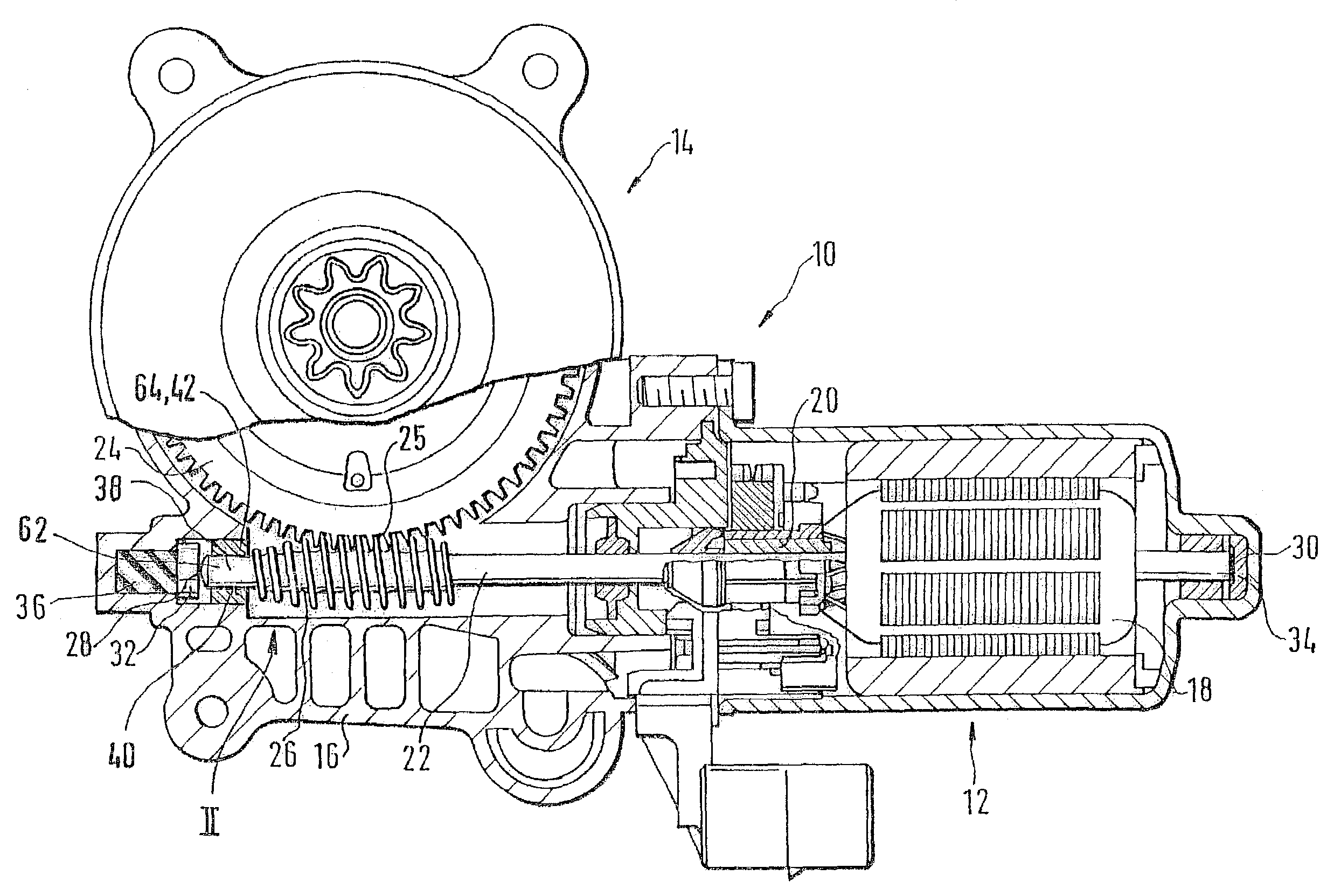
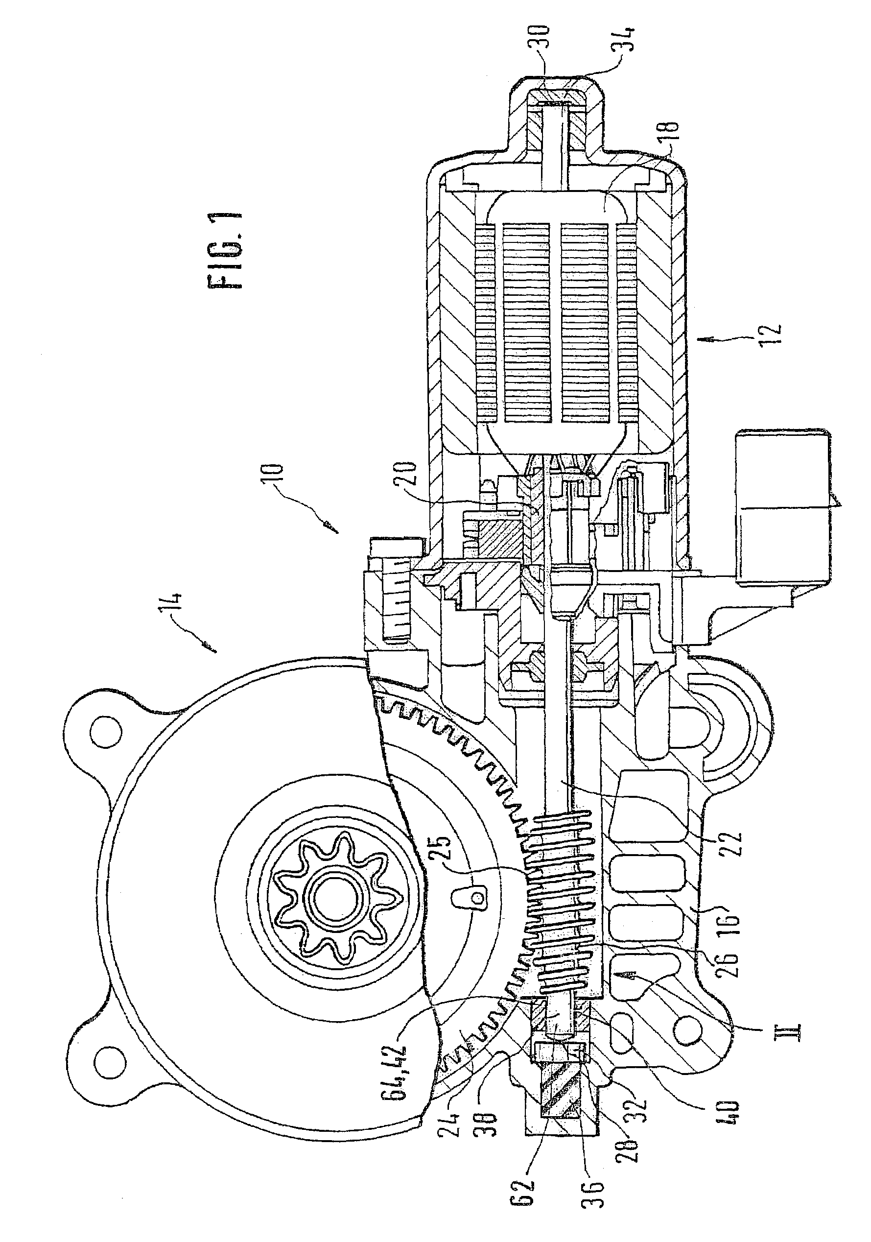
[0015]In FIG. 1, an adjusting drive 10 is shown, with a motor 12 and a multi-part housing 16 surrounding a gear 14. The motor 12 is commutated electrically and has an armature 18, a commutator 20, and an armature shaft 22, supported at multiple points, which extends into the region of the gear 14. A worm 26 is mounted on the armature shaft 22 and communicates with a worm wheel 24 via a set of teeth 25. On the face ends 28 and 30 of the armature shaft 22, this shaft is braced longitudinally on the housing 16, or part of the housing 16, via stop disks 32 and 34, and via a rubber insulator 36. A bearing surface 40 is formed onto one end 38 of the armature shaft 22 by means of positive displacement of material. This bearing surface 40 is guided in a shaft bearing 42, to prevent the armature shaft 22 from escaping from the teeth 25.

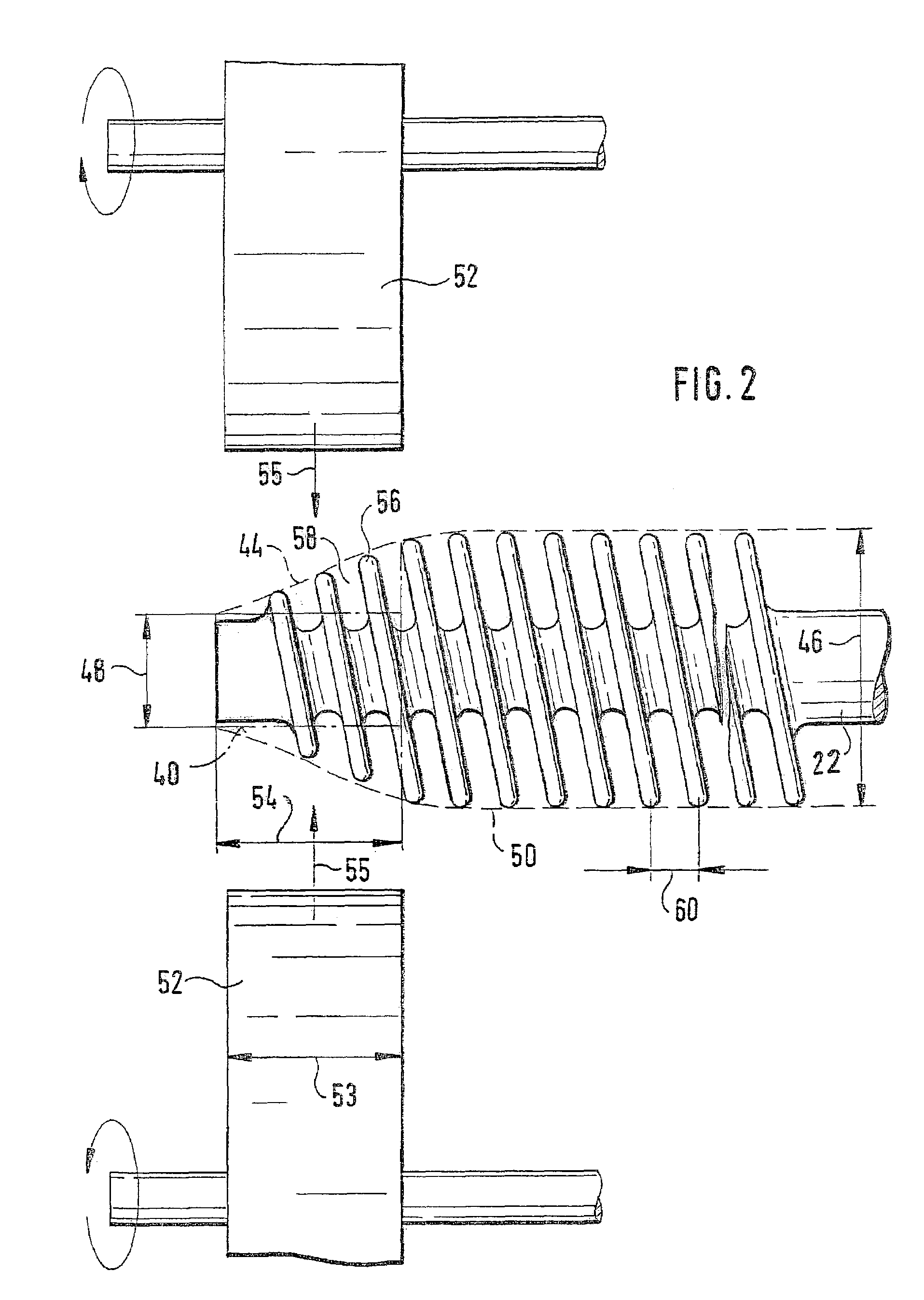
[0016]FIG. 2, showing an enlargement of the end 38 of the armature shaft 22, schematically illustrates the production process of the bearing surface 40. First...


PUM

PropertyMeasurementUnit
displacementaaaaaaaaaa
widthaaaaaaaaaa
torqueaaaaaaaaaa

Abstract

A method for producing a shaft and a device containing such a shaft (22), in particular an armature shaft (22) of an electric motor drive (10), which shaft is held by at least one shaft bearing (43), includes forming a bearing surface (40) for guidance in a shaft bearing (42) onto the shaft (22) at at least one point by positive displacement of material.

Description

BACKGROUND OF THE INVENTION[0001]The invention relates to a method for producing a shaft and to a device containing such a shaft [as generically defined by the preambles to the independent claims].[0002]With German Utility Model GM 297 02 525.2, a device has become known that is used for instance for displacing windows, sliding roofs, or seats. The object of this teaching is to avoid unwanted longitudinal play of an armature shaft, by means of a rubber insulator attached to the face end. A worm is pressed onto the armature shaft and transmits the torque of the electric motor to the worm wheel. The forward end of the armature shaft is guided in a rotary bearing receiving bush. This prevents the worm from deviating radially and thereby interfering with the meshing of the worm and wheel or destroying teeth. This is especially important when strong radial forces occur between the worm and the worm wheel, especially whenever the adjusting part runs up against a stop. From a production st...

Claims


Application Information

Patent Timeline
Patent Type & Authority Patents(United States)
IPC IPC(8): F16H1/16B21H3/02B21H5/00B21K1/12
CPCB21H5/005B21K1/12Y10T29/49471Y10T74/19828Y10T74/19623F16H1/16B21K1/06
Inventor FAUTH, LOTHAR
Owner ROBERT BOSCH GMBH
Why Eureka
Try Eureka