
Atomizer for coating unit and method for its material supply

a technology of atomizer and coating unit, which is applied in the direction of burners, electric spraying apparatus, combustion types, etc., can solve the problems of large space requirements of dosing cylinders, adverse effects of painting robots or other handling machines, and increase design costs and weight, etc., to achieve the effect of simple design

Inactive Publication Date: 2006-05-30
DURR SYST INC
View PDF60 Cites 6 Cited by
  • Summary
  • Abstract
  • Description
  • Claims
  • Application Information

AI Technical Summary

Benefits of technology

[0003]Such atomizers permit, among other things, advantageous paint change concepts and simple potential separation between electrostatic atomization devices operating with direct charging of the coating material and the paint supply system grounded for safety reasons, since the supply vessels are separated during coating from the grounded supply system and can be simply and automatically replaced for a paint change without or even with the actual atomizer. Known atomizers of this type contain dosing cylinders operated mechanically by a spindle drive (DE 196 10 588 A). Such dosing cylinders, however, have large space requirements stemming from their design. Their length, which is about twice as great as the piston stroke because of the piston rod, has an adverse effect mostly on painting robots or other handling machines on the accessibility of workpiece regions, such as vehicle interiors. Atomizers with hydraulically driven dosing cylinders are also already known (EP 0 967 016 A), whose compressed fluid, however, must be fed by a dosing pump located outside the atomizer.
[0005]The objective of the invention is to provide a simply designed, reliable and not too heavy atomizer, whose feeding means suffices without hydraulic dosing and can be accommodated in a limited space, as well as a corresponding method for material supply of the atomizer.
[0007]The invention is suitable especially, but not exclusively, for electrostatic atomizers that are mounted as a whole replaceably on painting robots or other coating machines and permit in simple fashion both the required potential separation from the grounded supply system of the coating unit and rapid and problem-free paint changes without significant losses of paint and rinsing agents with an arbitrary number of selectable paints. For example, in the case of painting robots, it is also advantageous that costly hose lines can be dispensed with within the machine, since the internal feeding means of the atomizer can be filled with the atomizer disassembled.
[0008]The preferred design of a dosing pump designed as a geared pump in the atomizer has the advantage that a dosing cylinder of known type is unnecessary in this conventional, reliable component that has long proven itself.
[0009]The structure of the paint supply vessel as a wound tube has the advantage that, on the one hand, because of the significant reduction in diameter in comparison with ordinary cylindrical paint vessels, correspondingly lower paint change losses and losses of rinsing agent occur and, on the other hand, the design flexibility is improved especially with respect to space savings. The same applies to the likewise possible use of one or more rigid coiled pipes as paint supply vessel(s).

Problems solved by technology

Such dosing cylinders, however, have large space requirements stemming from their design.
Their length, which is about twice as great as the piston stroke because of the piston rod, has an adverse effect mostly on painting robots or other handling machines on the accessibility of workpiece regions, such as vehicle interiors.
Moreover, general problems develop in dosing cylinders, like high requirements on support and bearing to guarantee the desired dosing accuracy and dynamics, which not only increase the design expense, but also the weight of the atomizer to be supported by the wrist joint of a robot.

Method used


Image

  • Atomizer for coating unit and method for its material supply
  • Atomizer for coating unit and method for its material supply
  • Atomizer for coating unit and method for its material supply

Examples


Embodiment Construction

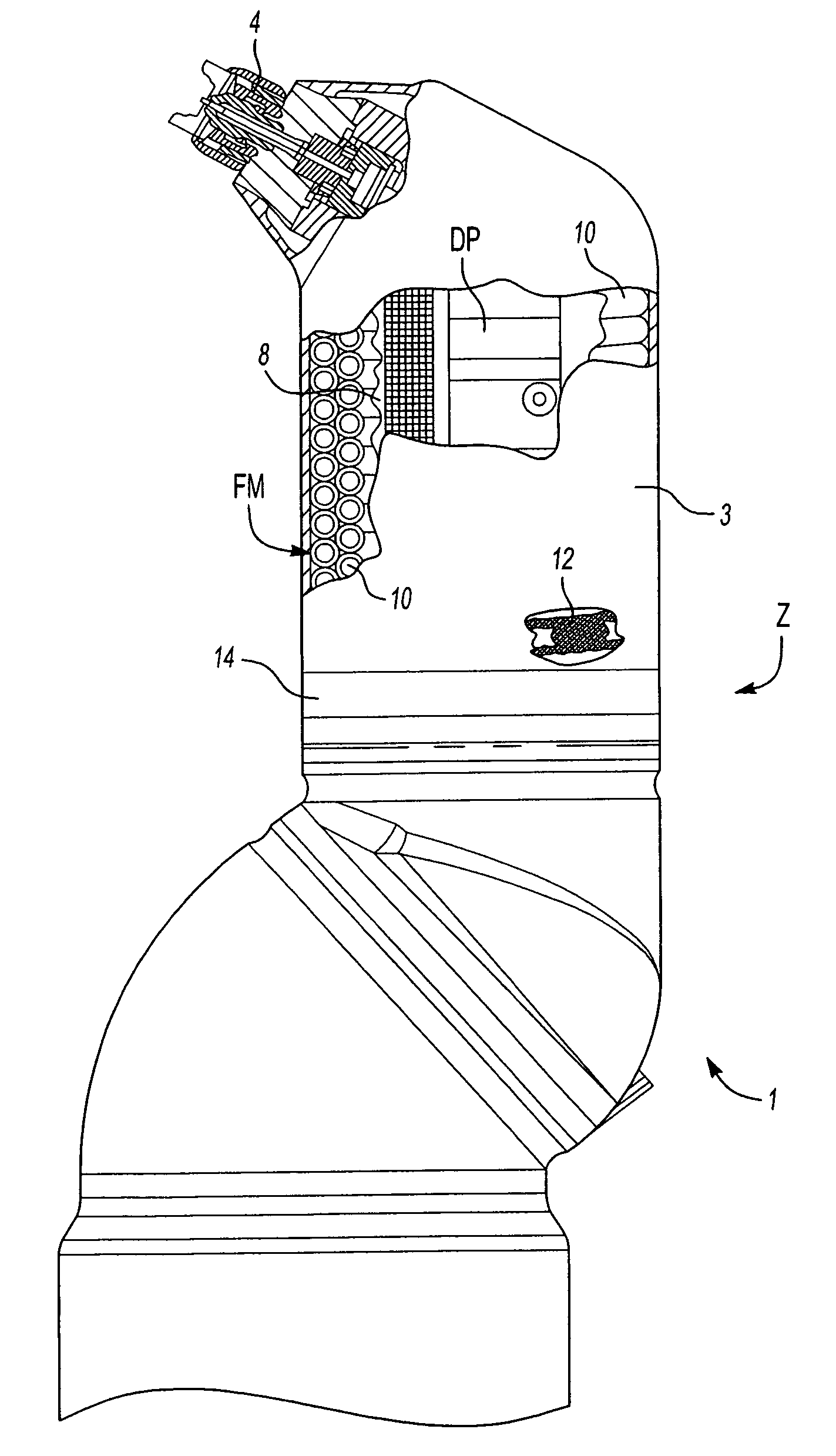
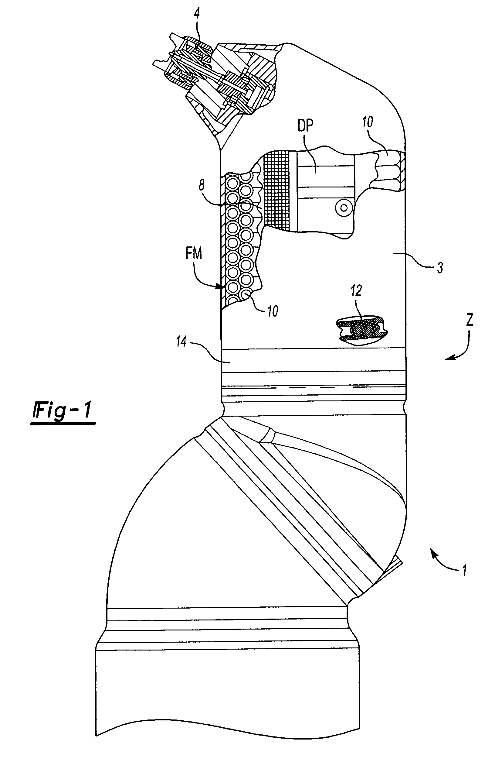
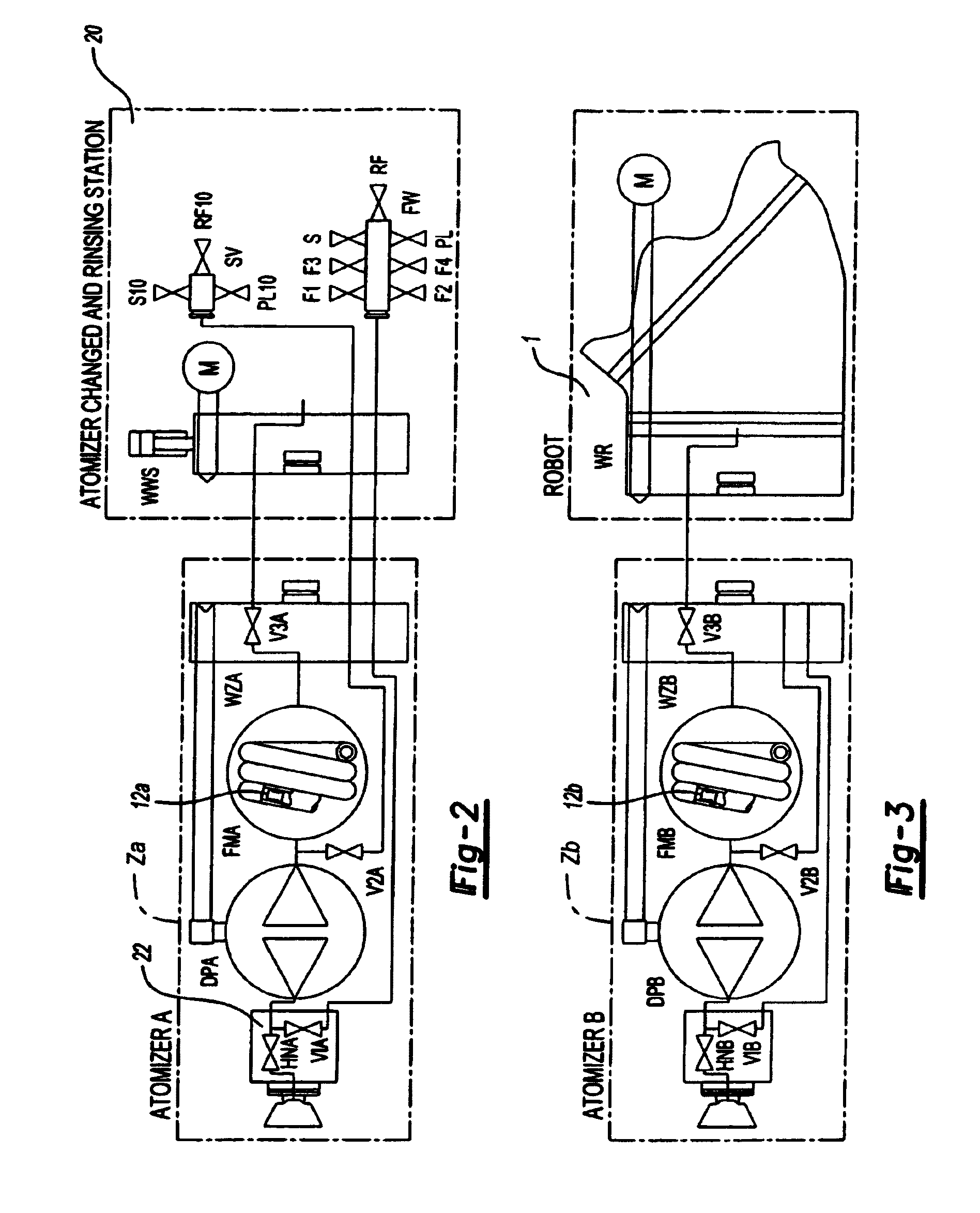
[0015]According to FIG. 1, an atomizer Z is mounted on wrist joint 1 of a robot, in whose housing 3 an air atomization device arranged in the front region, whose design and method of function are known and therefore require no explanation. The essentially cylindrical main part of housing 3 contains a dosing pump DP arranged coaxially in the middle of the housing, for example, a geared pump with an also known method of operation. The dosing pump DP is connected to atomization device 4 via valve unit 22 (FIG. 2) and can be controlled to convey in two opposite directions. The drive (not shown) of the dosing pump DP is expediently designed mechanically, for example, with a flexible shaft, which can be driven in turn via bevel gears and a pinion drive on the robot axis (by doubling of the robot axis usually referred to as axis 6). Another possibility is direct drive of the dosing pump DP by an electric motor situated in the atomizer.

[0016]A paint wound tube 10 of the shown two-layer coil...


PUM


Abstract

The atomizer (Z) of an electrostatic coating unit contains a dosing pump (DP) connected between the atomization device (4) and a scrapeable coiled pipe (10) which serves as a space-saving paint supply vessel and which is also situated in the atomizer. The scraper (12) is activated by compressed air on one side in order to force the paint material fed to its other side to the dosing pump (DP), which conveys it to the atomization device (4).

Description

RELATED APPLICATIONS[0001]This application is a continuation of and claims priority to U.S. patent application Ser. No. 10 / 360,782 and filed Mar. 16, 2002 and German Application No. 101 15 463.1 filed Mar. 29, 2001.[0002]The invention concerns an atomizer and a method for material supply of an atomizer for a coating machine according to the preamble of the independent claims. The atomizer, in particular, is an electrostatic rotary or air atomizer mounted as a complete unit replaceably on a painting robot or other coating machine for the sequential coating of workpieces, such as vehicle bodies.[0003]Such atomizers permit, among other things, advantageous paint change concepts and simple potential separation between electrostatic atomization devices operating with direct charging of the coating material and the paint supply system grounded for safety reasons, since the supply vessels are separated during coating from the grounded supply system and can be simply and automatically repla...

Claims


Application Information

Patent Timeline
IPC IPC(8): B05B15/02B05B5/16B05B12/14
CPCB05B5/1625B05B12/1481B05B12/14
Inventor GIULIANO, STEFANO
Owner DURR SYST INC
Learn More