Device for displacement of small liquid volumes along a micro-catenary line by electrostatic forces

a micro-catenary and electrostatic force technology, applied in laboratory apparatus, information storage, instruments, etc., can solve the problems of limiting reaction efficiency, introducing a large number of difficulties in the miniaturization section of ducts, and difficult to control the fluid displacement in these micro-ducts

Active Publication Date: 2006-05-30
COMMISSARIAT A LENERGIE ATOMIQUE ET AUX ENERGIES ALTERNATIVES
View PDF5 Cites 378 Cited by
  • Summary
  • Abstract
  • Description
  • Claims
  • Application Information

AI Technical Summary

Benefits of technology

[0028]Preferably, the conducting wire is wetting for the small liquid volume. This provides better guidance of the small liquid volume by the micro-catenary line.
[0029]The first electrically conducting means and / or the second electrically conducting means may possibly be covered with a layer of electrically insulating material. If the liquid to be displaced is electrically conducting, this enables insertion of an insulating layer so as to not create intense electric currents through the liquid droplet.
[0030]The device may include an ambient medium in which the small liquid volume displaces, this ambient medium being composed of a gas or liquid that is not miscible with the small liquid volume. For example, if the liquid to be displaced is composed of an aqueous solution, the ambient medium might be an oil bath. This prevents evaporation of the liquid when a long protocol is applied at high temperature.
[0036]According to a third variant embodiment, the substrate provides a surface with asymmetric roughness to the small volume of liquid, the distance between the conducting wire and the substrate being such that the small volume of liquid is in contact with the substrate under the effect of the applied electrostatic forces, and the substrate, due to its surface with asymmetric roughness, facilitates the displacement of the small liquid volume. The surface with asymmetric roughness may have a saw tooth type profile. The surface provided by the substrate to the small liquid volume may advantageously be unwetting.

Problems solved by technology

However, miniaturizing the section of ducts also introduces a large number of difficulties.
Firstly, it is difficult to control fluid displacements in these micro-ducts.
Secondly, physicochemical interactions between liquids and the walls become predominant.
Similarly, phenomena for absorption of biological entities at the wall surface can limit reaction efficiencies.
Another difficulty with micro-fluidics in micro-ducts is connecting the component to the outside world.
Connection of capillaries to a micro-component is one difficulty encountered in making labs on chips.
The disadvantage of the devices described above is that the droplets have to be confined between two planes or in a duct.
This makes assembly and use of the component complex.
Capillary connection problems arise that have already been identified for micro-fluidics in ducts, in which electrical connections also have to be taken into account.
There are also risks of phenomena for absorption of biological entities on the two planes confining the droplets.
Unlike the previous examples, this method requires a large number of electrodes.
This can be very limiting for some biological applications, in which the addition of reagents makes the liquids wetting.

Method used


Image

  • Device for displacement of small liquid volumes along a micro-catenary line by electrostatic forces
  • Device for displacement of small liquid volumes along a micro-catenary line by electrostatic forces
  • Device for displacement of small liquid volumes along a micro-catenary line by electrostatic forces

Examples


Embodiment Construction

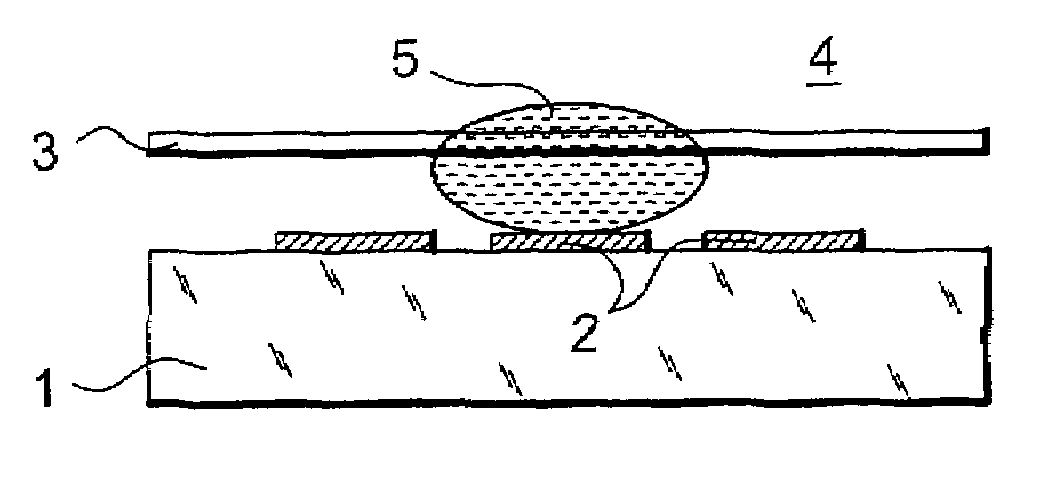
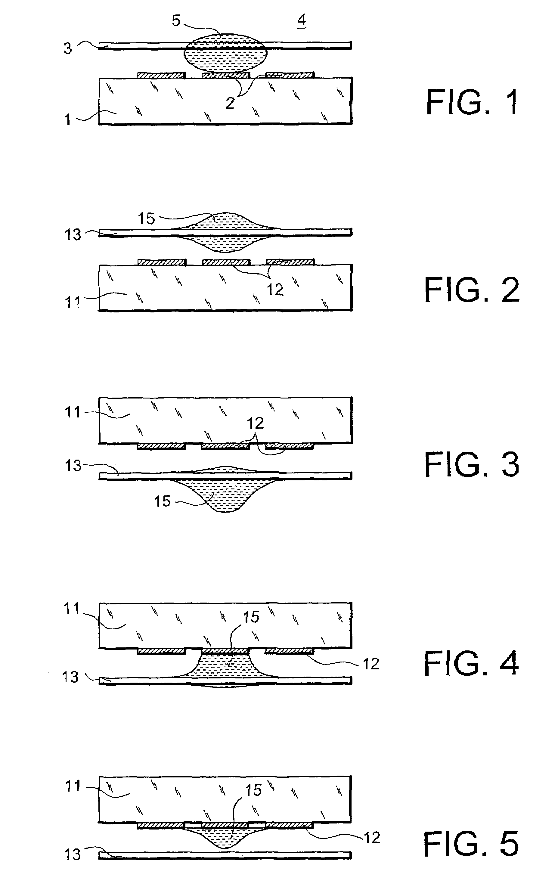
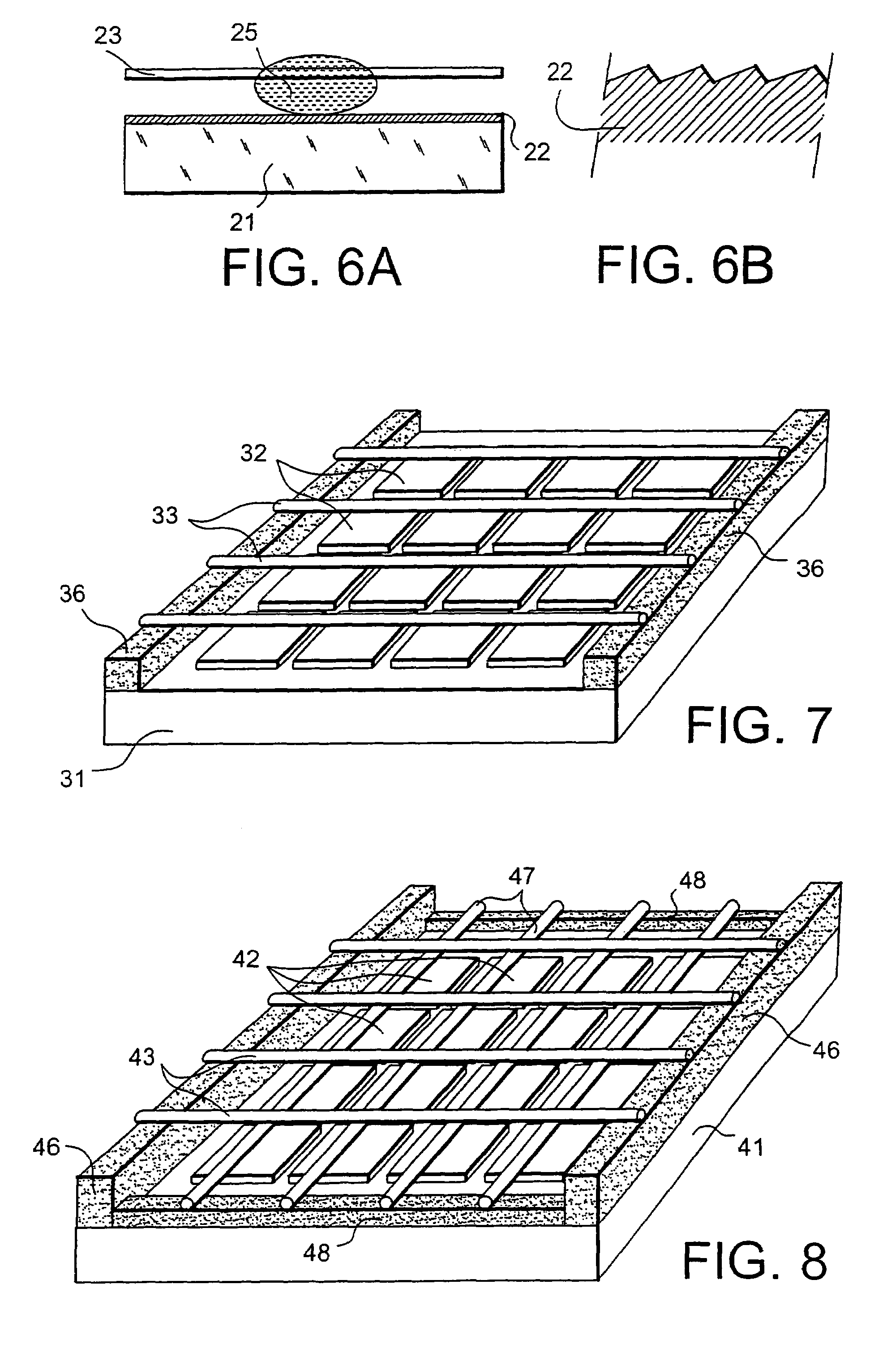
[0057]The first variant of the invention is shown in FIG. 1. The device shown, that may be called a chip, comprises a plane substrate 1, preferably made of an insulating material. One of the faces of the substrate 1 comprises electrodes 2 aligned along the direction specified for the displacement of micro-droplets. A conducting wire 3 or micro-catenary line is arranged approximately parallel to the substrate 1 and at a determined distance from this substrate. The micro-catenary line 3 is facing the electrodes 2. The assembly is immersed in an ambient medium 4 that may be a gas or a liquid that is not miscible with the liquid in the micro-droplet 5.

[0058]The device according to the invention deforms or displaces the droplet 5 by the application of an electric field between the micro-catenary line and at least one of the electrodes 2. The displacement of the droplet can be explained with reference to prior art mentioned above, in relation to electrostatic forces.

[0059]Since the micro-...


PUM

PropertyMeasurementUnit
voltagesaaaaaaaaaa
diameteraaaaaaaaaa
diameteraaaaaaaaaa

Abstract

The invention relates to a device for displacement of at least a small volume of liquid (5) under the effect of an electrical control, including a substrate (1) provided with first electrically conducting means (2), the device also comprising second electrically conducting means (3) arranged facing the first electrically conducting means (2), the first electrically conducting means and the second electrically conducting means possibly being connected to electrical power supply means to enable the application of electrostatic forces to the small liquid volume (5). The second electrically conducting means include at least one conducting wire (3) arranged parallel to the substrate and at a fixed distance from the substrate to enable displacement of the small volume of liquid (5) along said conducting wire (3) under the effect of the applied electrostatic forces.

Description

BACKGROUND OF THE INVENTION[0001]1. Field of the Invention[0002]The invention relates to a device for manipulation of small volume droplets consisting of a few nanoliters to a few microliters. The displacement device uses electrostatic forces to displace small liquid volumes.[0003]2. Description of the Background Art[0004]Liquids are increasingly important in small components. Thus, labs-on-chips are used in many studies, mainly for biology, chemistry and optics. In some cases, micro-fluidics consists of making small volumes of liquid circulate in micro-machined ducts. For example, this means that a biological protocol can be applied on a very small sample volume. At the present time it is recognized that there are many advantages in minimizing analysis volumes, for example cost reductions, and improved speed and sensitivity.[0005]However, miniaturizing the section of ducts also introduces a large number of difficulties. Firstly, it is difficult to control fluid displacements in the...

Claims


Application Information

Patent Timeline
Patent Type & Authority Patents(United States)
IPC IPC(8): F04F11/00G11C13/00B01L3/00F04B17/00F04B19/00F04F99/00G01N35/10H02N11/00
CPCB01L3/502792H02N11/006F04B17/00F04B19/006B01L2300/0845B01L2300/089B01L2300/1827G01N2035/1046B01L2400/0415
Inventor FOUILLET, YVESCHARLES, RAYMONDCONSTANTIN, OLIVIERJEANSON, HUBERT
Owner COMMISSARIAT A LENERGIE ATOMIQUE ET AUX ENERGIES ALTERNATIVES
Why Eureka
Try Eureka