Method and a device for cleaning of crankcase gases coming from an internal combustion engine adapted for propelling a means of transportation

a technology of internal combustion engine and cleaning method, which is applied in the direction of combustion-air/fuel-air treatment, centrifuges, separation processes, etc., can solve the problem that the cleaning method is not suitable in connection with the combustion engin

Inactive Publication Date: 2006-05-30
ALFA LAVAL CORP AB
View PDF3 Cites 9 Cited by
  • Summary
  • Abstract
  • Description
  • Claims
  • Application Information

AI Technical Summary

Benefits of technology

[0015]However, according to a preferred embodiment of the invention the auxiliary fluid channel communicates, instead, with a special auxiliary fluid nozzle. Then, said throttling member may be formed by the auxiliary fluid nozzle itself. This is particularly advantageous if the auxiliary pressurized air has a pressure exceeding about 2 bars, for in such a case the energy of the auxiliary pressurized air may be used in a very efficient way by use of a so called De Laval-nozzle as an auxiliary fluid nozzle. By means of a nozzle of this kind the auxiliary pressurized air may be brought to a speed exceeding the speed of sound, which creates possibilities for an efficient driving of the centrifugal rotor with a high rotational speed—resulting in an efficient cleaning of the crankcase gases—even by means of the auxiliary pressurized air.
[0020]A particularly simple and inexpensive use of the invention can be obtained if

Problems solved by technology

However, the cleaning method is not suitable in connection with a combustion engine that is adapted for propelling of a vehicle, since cleaning performed in this way would be heavily reduced or completely fail to take place during periods when the vehicle stands still but the combustion engine is idling or when the vehicle is moving without being propelled by means of the combustion engine.

Method used


Image

  • Method and a device for cleaning of crankcase gases coming from an internal combustion engine adapted for propelling a means of transportation
  • Method and a device for cleaning of crankcase gases coming from an internal combustion engine adapted for propelling a means of transportation
  • Method and a device for cleaning of crankcase gases coming from an internal combustion engine adapted for propelling a means of transportation

Examples


Embodiment Construction

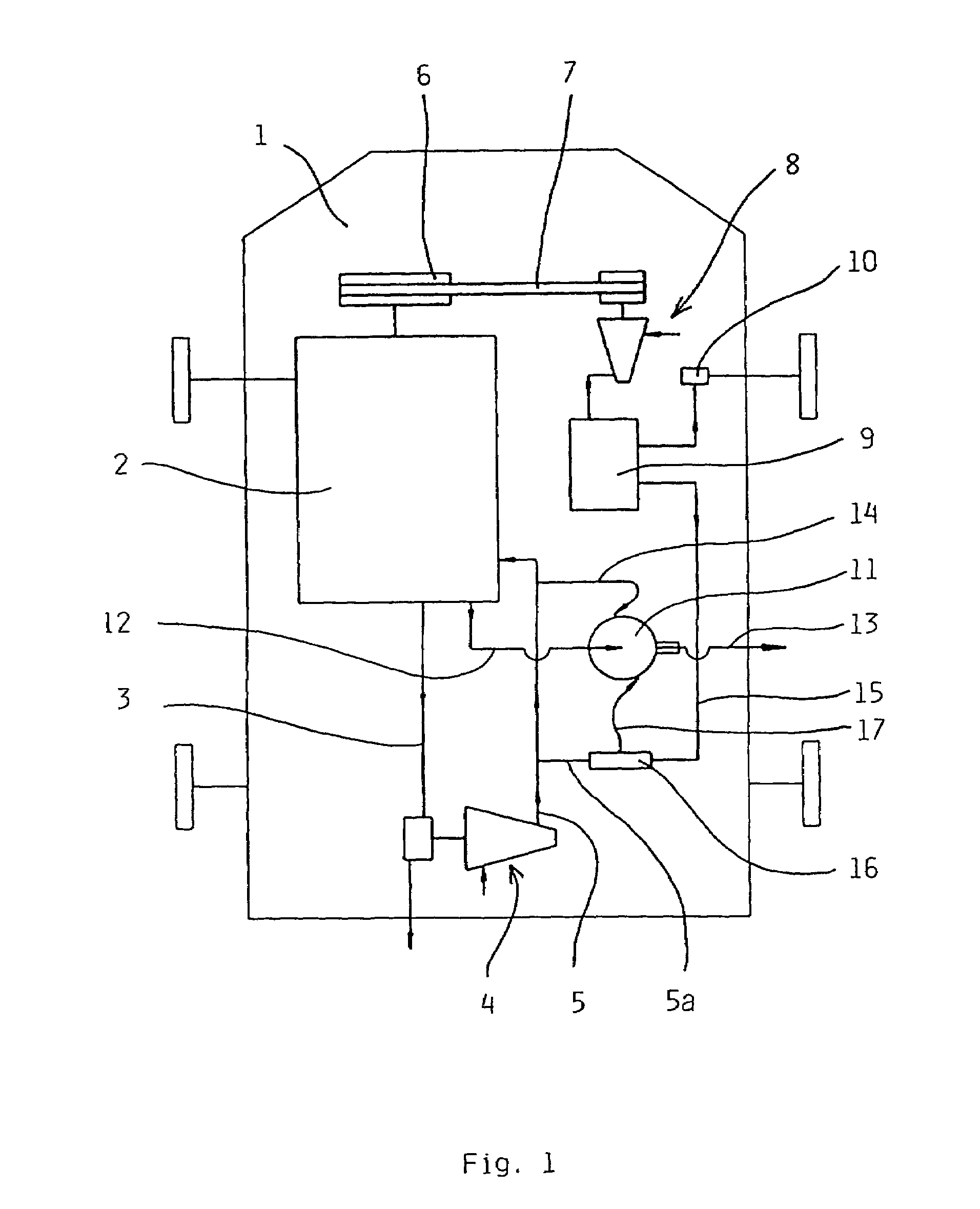
[0034]FIG. 1 shows schematically a vehicle 1, that is adapted to be propelled by means of an internal combustion engine 2. An exhaust pipe 3 is adapted to conduct away exhaust gases from the motor 2 via a so called turbo compressor 4. Compressed air is conducted from the turbo compressor 4 through a conduit 5 to the motor 2, in which it is supplied into the combustion room thereof (not shown). Upon propelling of the vehicle 1 the exhaust gases of the motor accomplish that the turbo compressor generates an overpressure, normally in the order of 0.5–2 bars, in the conduit 5.

[0035]Through a belt disc 6 and a belt 7 the motor 2 is adapted to drive also a compressor 8 for delivering pressurized air to a container 9. The pressure in this container is maintained at a pressure in the order of 8–12 bars, i.e. a pressure substantially larger than the pressure accomplished by the turbo compressor 4 in the conduit 5. From the container 9 pressurized air, upon need, is conducted to the braking s...


PUM

PropertyMeasurementUnit
pressureaaaaaaaaaa
pressureaaaaaaaaaa
air pressureaaaaaaaaaa

Abstract

In a vehicle adapted to be propelled by means of an internal combustion engine crankcase gases coming from the combustion engine are cleaned by means of a centrifugal separator. The rotor of the centrifugal separator is driven by means of pressurized air delivered by a compressor, e.g. a so called turbo compressor, which is driven by means of the combustion engine. During periods when the compressor delivers pressurized air in an insufficient amount and / or at insufficient pressure the rotor of the centrifugal separator is instead driven by means of pressurized air coming from a container containing so called auxiliary pressurized air. The auxiliary pressurized air may have a substantially larger pressure than the pressurized air normally delivered by the compressor. The combustion engine is used also for accomplishing the overpressure of the auxiliary pressurized air in the container.

Description

CROSS-REFERENCE TO RELATED APPLICATIONS[0001]This application is entitled to the benefit of and incorporates by reference essential subject matter disclosed in International Patent Application No. PCT / SE01 / 02394 filed on Oct. 31, 2001 and Swedish Patent Application No. 0004459-4 filed on Dec. 1, 2000.FILED OF THE INVENTION[0002]The present invention primarily relates to a method of cleaning crankcase gases coming from an internal combustion engine, that is adapted for propelling a means of transportation, e.g. a car or a vessel, in the following named a vehicle. More closely the invention relates to a method of this kind, in which a centrifugal rotor is used for the cleaning, driven by means of pressurized air delivered from a compressor which, in turn, is driven by means of the combustion engine, e.g. an exhaust gas driven compressor—often named turbo compressor—adapted for generation and supply of pressurized air to the combustion room of the motor.BACKGROUND OF THE INVENTION[0003...

Claims


Application Information

Patent Timeline
Patent Type & Authority Patents(United States)
IPC IPC(8): B01D45/14B04B5/00B04B5/08B04B5/12B04B9/06F01M13/04
CPCB01D45/14B04B5/005B04B5/08B04B5/12F01M13/04B04B9/06Y10S55/19B04B2005/125F01M2013/0422
Inventor FRANZEN, PETERHALLGREN, INGVARLARSSON, LEIF
Owner ALFA LAVAL CORP AB
Why Eureka
Try Eureka