
Power generating system including a high-frequency alternator, a rectifier module, and an auxiliary power supply

a technology of rectifier module and high-frequency alternator, which is applied in the direction of electric generator control, dynamo-electric converter control, single ac network with different frequencies, etc., can solve the problems of reducing the rated terminal voltage at the rated current, reducing both power output and efficiency, and reducing the rated load. , the effect of reducing the rated load

Active Publication Date: 2006-05-30
CAPSTONE GREEN ENERGY CORP +1
View PDF6 Cites 56 Cited by
  • Summary
  • Abstract
  • Description
  • Claims
  • Application Information

AI Technical Summary

Benefits of technology

"The invention is a power generating system that includes a high-frequency alternator with capacitors retained within output lines to maintain a small difference between unloaded operation and operation at a rated power. The system also includes an auxiliary power supply using alternating current generated by the alternator without substantially degrading the output power that can be generated. The system further includes a convenient modular device for attachment to a high-frequency polyphase alternator to rectify output current produced by the alternator and to provide capacitance needed for voltage regulation. The technical effects of the invention include improved voltage regulation and reduced voltage fluctuations, as well as improved stability and efficiency of power generation."

Problems solved by technology

One problem that has been identified with this type of generating system arises from the substantial internal inductive reactance of the alternator, which causes the output voltage of the alternator at its rated load to be significantly lower than its unloaded output voltage.
The reduction in the rated terminal voltage at the rated current, which reduces both power output and efficiency, is present in any machine that includes significant internal inductive reactance.
However, the addition of an inductive load, such as the windings of a polyphase transformer to provide power for auxiliary functions needed to run the microturbine, to the output terminals of such capacitors wired in series with a polyphase alternator has proven to increase the current flowing through the capacitors and out windings of the alternator in a way that places an undesirable limitation on the power that can be produced by the alternator.

Method used


Image

  • Power generating system including a high-frequency alternator, a rectifier module, and an auxiliary power supply
  • Power generating system including a high-frequency alternator, a rectifier module, and an auxiliary power supply
  • Power generating system including a high-frequency alternator, a rectifier module, and an auxiliary power supply

Examples


Embodiment Construction

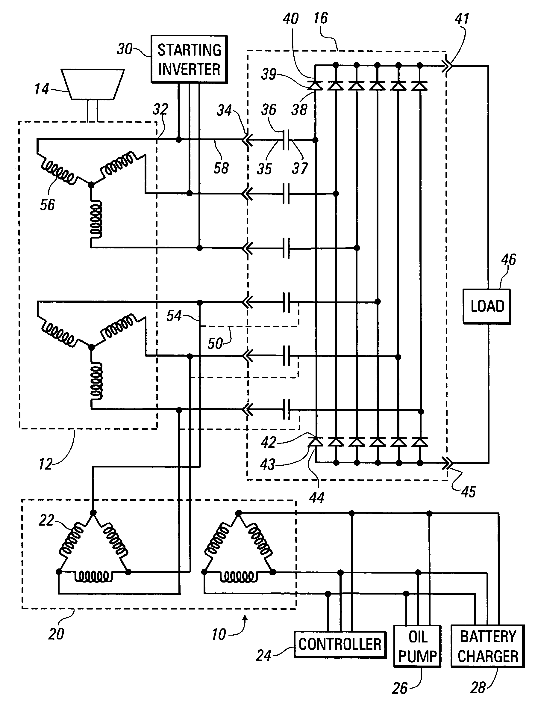
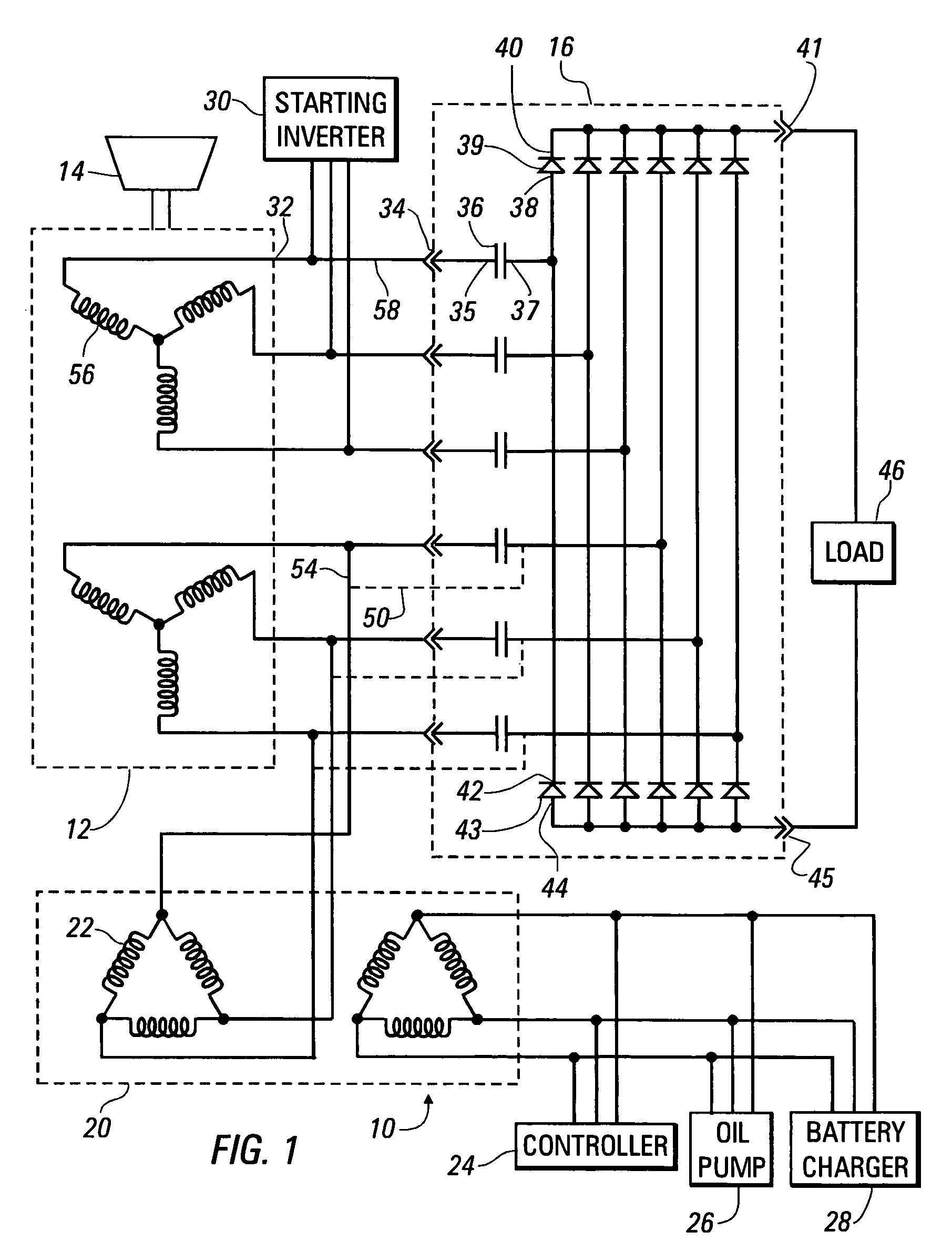
[0022]FIG. 1 is a schematic view of an electrical power generating system 10, built in accordance with the present invention to include a high-frequency six-phase alternator 12, driven by a microturbine 14, a rectifier module 16 converting high-frequency alternating current to direct current, and an auxiliary power supply 20 including a three-phase transformer with primary windings 22. The auxiliary power supply 20 provides power for auxiliary functions associated with operation of the microturbine 14, such as the operation of a controller 24, an oil pump 26 and a battery charger 28, which charges one or more batteries to provide power for a starting inverter 30, which is used to start the microturbine 14, with the alternator 12 operating as a motor having a three-phase alternating current input applied at three of its terminals 32.

[0023]In accordance with the invention, the rectifier module 16 includes an input terminal 34 connected to each of the output terminals 34 of the alterna...


PUM


Abstract

A power generating system includes a high-frequency alternator, a rectifier, a capacitor in each phase line extending between an output terminal of the alternator and the rectifier, and an auxiliary power supply, providing auxiliary power for use within the power generating system, which is also connected to the output terminals of the alternator.

Description

BACKGROUND OF THE INVENTION[0001]1. Field of the Invention[0002]This invention relates to an electrical power generating system including an alternator producing polyphase alternating current at a high frequency, and, more particularly, to a rectifier and an auxiliary alternating current power supply within such a power generating system.[0003]2. Summary of the Background Art[0004]A number of electrical generating systems employ a polyphase alternator driven at a high speed by a relatively small gas turbine, called microturbine, to produce polyphase alternating current at a high frequency, such as 2.3 kHz. This high-frequency alternating current is then rectified, producing direct current that can be used for other purposes, such as generating 50- or 60-Hz alternating current. Individual generating systems of this kind are used to produce a few kilowatts to a few megawatts of electrical power. An alternator of this type generates electricity through the use magnetic fields establish...

Claims


Application Information

Patent Timeline
Patent Type & Authority Patents(United States)
IPC IPC(8): H02P9/00H02P9/44
CPCH02J3/02H02M7/08H02M2001/009H02M1/009
Inventor WANG, QUINCY Q.
Owner CAPSTONE GREEN ENERGY CORP
Learn More