Fixation device for implantable microdevices

a technology of fixation device and implantable micro-device, which is applied in the field of implantable electrical stimulation device, can solve the problems of micro-stimulators that may migrate over time and become ineffective, may be thin and rather long, and may be prone to mechanical damag

Inactive Publication Date: 2006-05-30
BOSTON SCI NEUROMODULATION CORP
View PDF50 Cites 375 Cited by
  • Summary
  • Abstract
  • Description
  • Claims
  • Application Information

AI Technical Summary

Benefits of technology

[0011]The present invention addresses the above and other needs by providing a fixation device for microstimulators. The fixation device may either attach to a microdevice, and cooperate with surrounding tissue to prevent migration of the microdevice, or reside behind the microdevice in the implantation pathway, and thereby prevent retreat of the microdevice through the pathway. In one embodiment, the fixation device comprises a sheath adapted to attach the fixation device to the microdevice, and means for attaching the fixation device to surrounding tissue to prevent migration of the microdevice. Several embodiments of the fixation device exist, each constructed from a non-conducting material, except where specifically noted. Such material may further be resorbable.
[0015]In a fourth embodiment, the microdevice resides substantially outside of the grasping member. This allows the entire grasping member to maintain uniform contact with the tissue around which the grasping member is wrapped.

Problems solved by technology

Such microstimulators may migrate over time and become ineffective.
While leaded system have been successful in many applications, several potential disadvantages accompany their use.
The implantation procedure may be rather difficult and time-consuming, as the electrodes and the SCU must usually be implanted in separate areas, and the lead must be tunneled through body tissue to connect the electrodes to the SCU.
Also, the leads are typically thin and rather long and are thus prone to mechanical damage over time.
Additionally, many conventional systems typically consist of a relatively large SCU, which can have a negative cosmetic appearance if positioned subcutaneously.
Contraction of the muscles may cause the microstimulator to migrate significantly over time.
Additionally, the motion of limbs may exert unequal pressures on the microstimulator at almost any location within an extremity, which may also result in migration, especially along the pathway created during implantation.
As yet another example, some nerves are surround by firm but lubricious tissue, and such tissue may not provide sufficient fixation of the microstimulator.
The firm, lubricious carotid sheath is likely to offer little adhesion to the microstimulator, and actuation of the surrounding neck muscles may cause significant migration of the microstimulator, especially during the period immediately following implantation.

Method used


Image

  • Fixation device for implantable microdevices
  • Fixation device for implantable microdevices
  • Fixation device for implantable microdevices

Examples


first embodiment

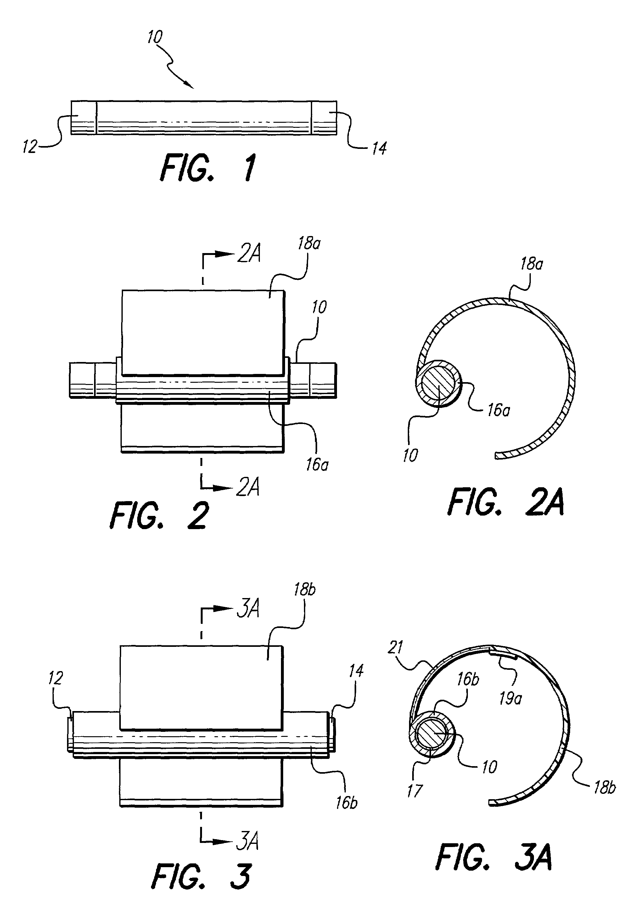
[0043]In some applications, for example Peripheral Nerve Stimulation (PNS), the microdevice 10 may require a fixation device to prevent migration of the microdevice 10 after implantation. In general, the fixation device comprises a holder suitable for holding the microdevice 10, and a means for attaching the fixation device to body tissue. the fixation device is shown in a side view in FIG. 2, with the fixation device comprising a first sheath 16a which holds the microdevice 10, and a first grasping member 18a to attach the microdevice to a nerve, muscle, or other body tissue.

[0044]A cross-sectional view of the first embodiment of a fixation device, taken along line 2A—2A of FIG. 2, is shown in FIG. 2A. A somewhat flexible curved member forms the grasping member 18a, with the sheath 16a residing substantially inside the arc of the grasping member 18a (i.e., most or all of the sheath 16a resides inside the circle defined by that arc of the grasping member 18a). The grasping member 18...

second embodiment

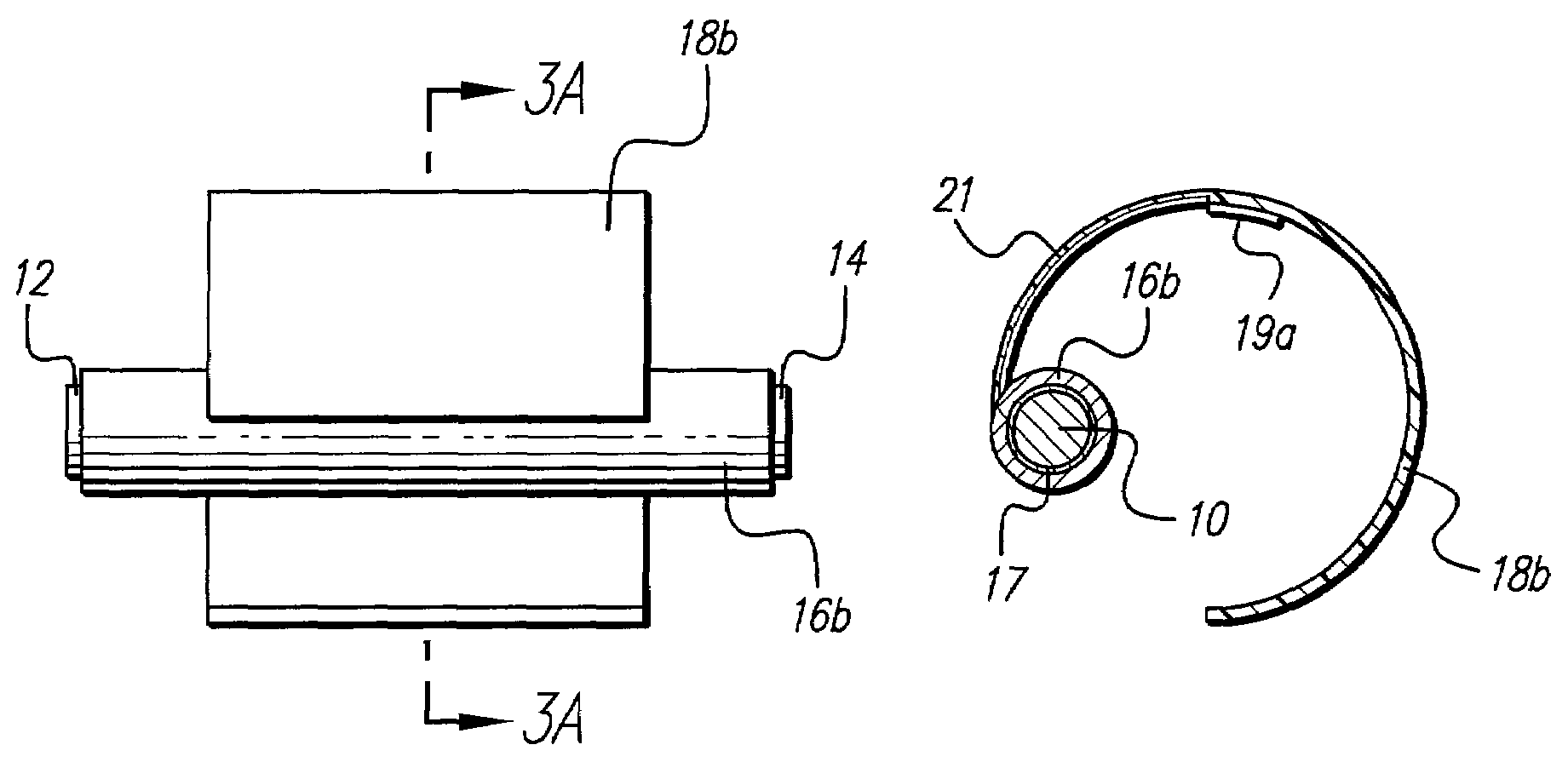
[0045]a fixation device is shown in FIG. 3 in a side view, and in FIG. 3A in a cross-sectional view taken along line 3A—3A of FIG. 3. A second grasping member 18b includes at least one first electrode 19a, which electrode 19a is electrically connected by at least one lead 21 to at least one contact 17 residing on the interior of a second sheath 16b. The contact 17 is adapted to cooperate with the microdevice 10 to provide an electrical connection between the lead 21 and electronics included in the microdevice 10, preferably through contact with the anode 12 or the cathode 14. However, those skilled in the art will recognize that the contact 17 may electrically connect to the microdevice 10 through some other special contact on the exterior of the microdevice 10. In a preferred embodiment, the contact 17 comprises a cylindrical or ring contact.

[0046]In the second embodiment, the anode 12 and the cathode 14 may be exposed to tissue, or may be covered and insulated, in whole or in part...

fourth embodiment

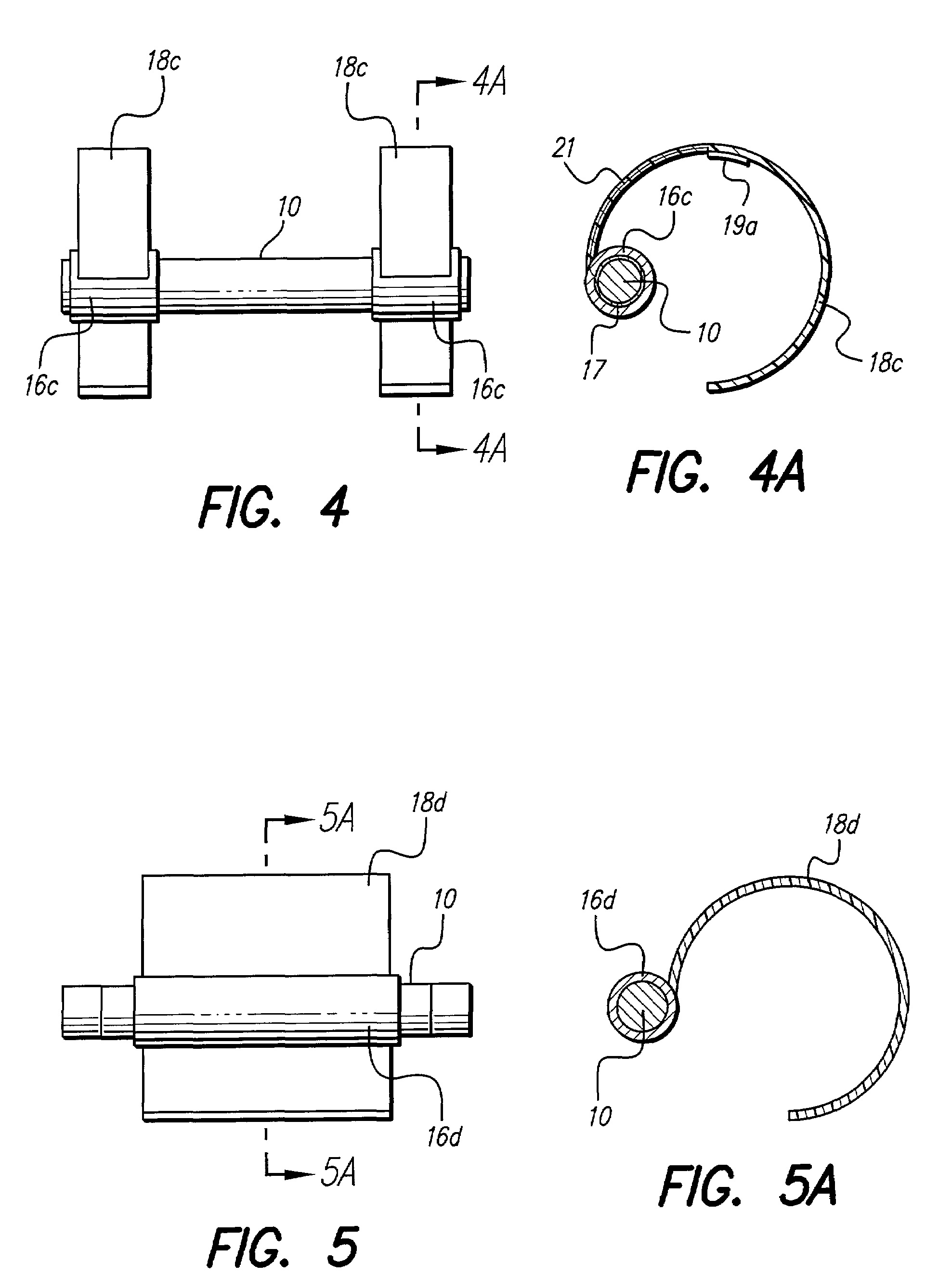
[0048]the fixation device is shown in a side view in FIG. 5 and in a cross-sectional view in FIG. 5A taken along line 5A—5A of FIG. 5, wherein a fourth sheath 16d resides substantially outside the arc of a fourth grasping member 18d (i.e., most or all of the sheath 16d resides outside the circle defined by that arc of the grasping member 18d). Electrodes may be included in the grasping member 18d as described for FIGS. 3 and 3A above, or the simulation or sensing may be provided solely by the anode 12 and the cathode 14. Further, the sheath 16d and grasping member 18d may be configured as two or more sheaths and grasping members as described in FIGS. 4 and 4A.

[0049]A fifth embodiment of the fixation device is shown in FIG. 6. The fifth embodiment includes at least one helix member, and preferably first and second helix members 20a and 20b, which wrap around the tissue 23, and may or may not include at least one fifth grasping member 18e. The helix members 20a and 20b, and the graspi...


PUM


Abstract

A fixation device fixes the position of an implantable microminiature device residing proximally to a target site such as a nerve or a muscle. In one embodiment, the device comprises a sheath and a means for attaching the device to adjacent tissue. The means for attaching may be any one of several embodiments including one or more grasping members, a combination of grasping members and one or more helices, or an extension adapted to accept a suture. In another embodiment, the fixation device comprises an assembly residing in the implantation pathway, behind the stimulation device, thus preventing retreat of the stimulation device in the pathway. In a preferred use, the fixation device fixes the position of a microstimulator component of a Peripheral Nerve Stimulation (PNS) system.

Description

[0001]The present application claims the benefit of U.S. Provisional Application Ser. No. 60 / 300,401, filed Jun. 22, 2001, which application is incorporated herein by reference.BACKGROUND OF THE INVENTION[0002]The present invention relates to implantable electrical stimulation devices and more particularly to the fixation of microstimulators included in Peripheral Nerve Stimulation (PNS) systems. Such microstimulators may migrate over time and become ineffective.[0003]Implantable electrical stimulation devices have proven therapeutic in a wide variety of diseases and disorders. Pacemakers and Implantable Cardiac Defibrillators (ICDs) have proven highly effective in the treatment of a number of cardiac conditions (e.g., arrhythmias). Spinal Cord Stimulation (SCS) systems have long been accepted as a therapeutic modality for the treatment of chronic pain syndromes, and the application of tissue stimulation has begun to expand to additional applications such as angina pectoralis and in...

Claims


Application Information

Patent Timeline
Patent Type & Authority Patents(United States)
IPC IPC(8): A61N1/05
CPCA61N1/375A61N1/37205A61N1/3756A61N1/37518
Inventor WHITEHURST, TODD KMCGIVERN, JAMES P
Owner BOSTON SCI NEUROMODULATION CORP
Why Eureka
Try Eureka