Air conditioning apparatus for vehicle

a technology for air conditioning apparatus and vehicle, which is applied in the direction of lighting and heating apparatus, heating types, instruments, etc., can solve the problems of reducing the efficiency of the engine, and affecting the operation of the air conditioner

Inactive Publication Date: 2006-06-06
CALSONIC KANSEI CORP
View PDF18 Cites 34 Cited by
  • Summary
  • Abstract
  • Description
  • Claims
  • Application Information

AI Technical Summary

Benefits of technology

[0006]In such a situation, it is an object of the present invention to prevent an occurrence of defects due to insufficient cool-down of a power source for driving a vehicle in an air conditioning apparatus for vehicle where a water-coolant heat exchanger for exchanging heat of the coolant of high temperature and high pressure for engine cooling water is arranged between a compressor and an outdoor heat exchanger.
[0008]With the above-mentioned constitution of the air conditioning apparatus, when the cooling water for the power source is more than the predetermined temperature, the cooling water is not introduced into the water-coolant heat exchanger. Therefore, as the temperature of the cooling water is not elevated, it is possible to prevent an occurrence of damage due to seizure of sliding parts about the power source for driving the vehicle.
[0010]In this configuration, by controlling the first expansion switching unit and the second expansion switching unit so that the coolant expands at the heat expansion unit, it is possible, at heating, to improve the heating performance of the air conditioning apparatus due to increased endothermic amount from the outdoor-side coolant heat exchanger.
[0012]In this configuration, by controlling the heat-exchanger switching unit so that the coolant avoids the outdoor-side coolant heat exchanger at the initial stage of heating, it is possible to improve the apparatus' quickness in heating since the air conditioning wind supplied to the vehicle cabin is not cooled down.
[0014]In this configuration, since the internal heat exchanger performs heat exchange between the coolant of high pressure and the coolant of low pressure, the temperature of the coolant of high-pressure is lowered at cooling. Therefore, it is possible to improve the efficiency of the coolant cycle.

Problems solved by technology

However, when a vehicle is at a stop where the velocity of cooling wind is remarkably small for the outdoor heat exchanger, the radiation efficiency is deteriorated remarkably.
Then, friction of sliding parts of the engine is increased to reduce the efficiency of the engine.
If the water temperature of the engine cooling water is remarkably high, there arises a possibility that the water temperature is further elevated as a result of heat-exchanging at the water-coolant heat exchanger, so that the sliding parts of the engine may be damaged (e.g. burn-in) because of insufficient cool-down of the engine.

Method used


Image

  • Air conditioning apparatus for vehicle
  • Air conditioning apparatus for vehicle
  • Air conditioning apparatus for vehicle

Examples


first embodiment

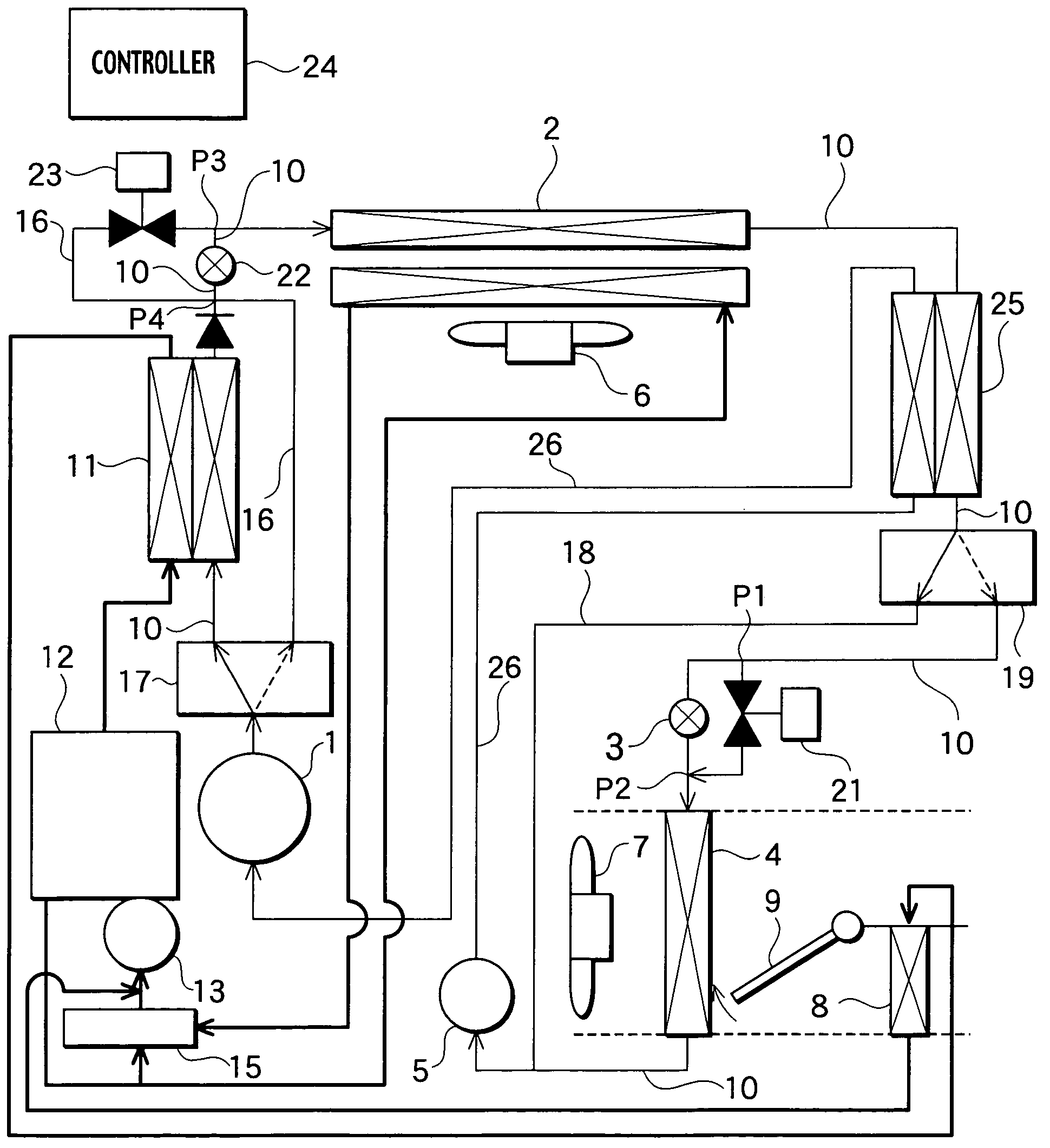
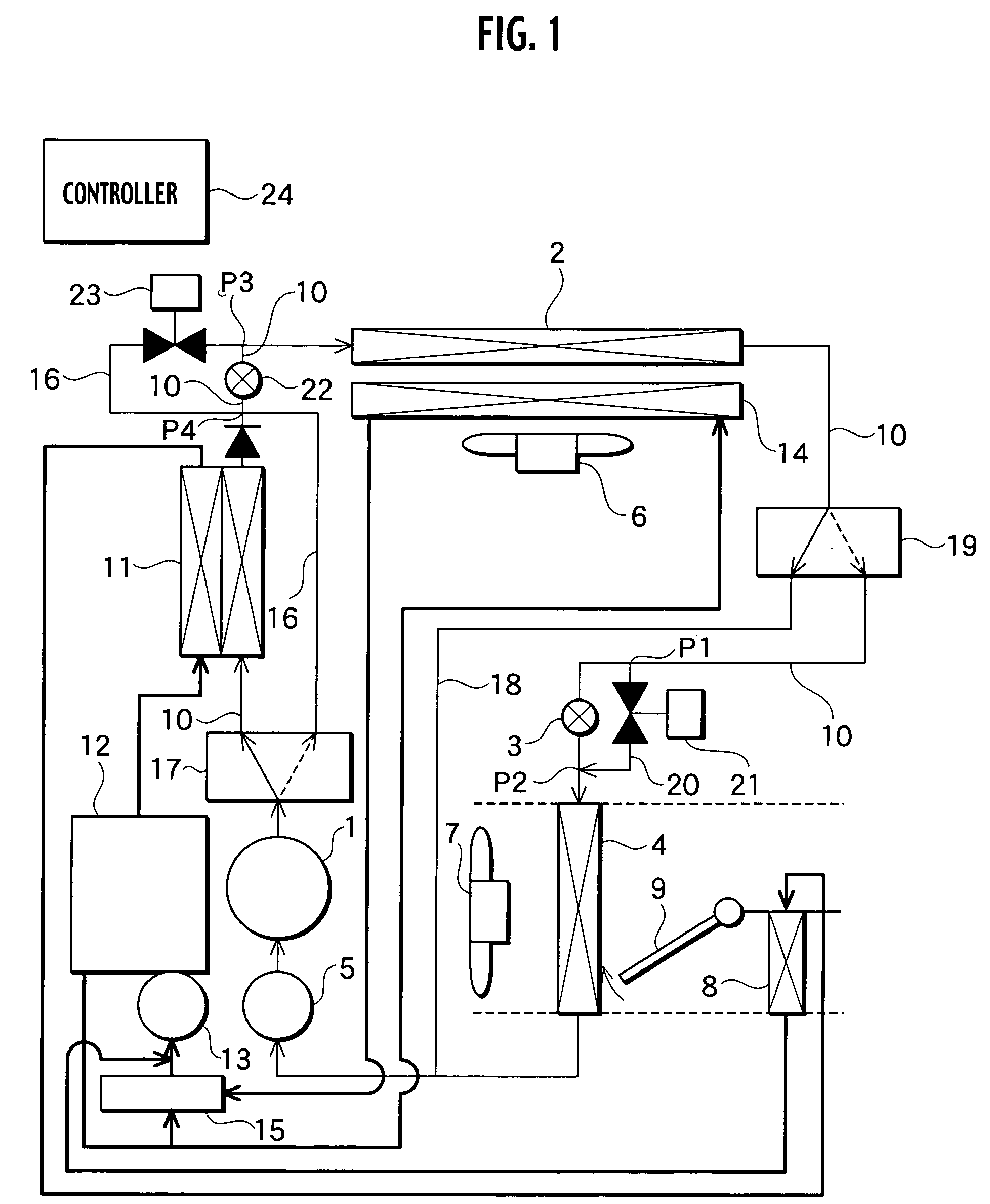
[0020]Embodiments of the present invention will be described with reference to the accompanying drawings. FIG. 1 is a schematic structural view of an air conditioning apparatus for a vehicle, in accordance with the present invention.

[0021]The air conditioning apparatus includes a compressor 1 for compressing coolant, a gas cooler 2 (as the outdoor-side coolant heat exchanger) that exchanges heat of coolant compressed by the compressor 1 for ambient air, a pressure control valve 3 (as the expansion unit) for adiabatically expanding the coolant after heat exchange at the gas cooler 2, an evaporator 4 (as the indoor-side coolant heat exchanger) that exchanges heat of the coolant expanded at the pressure control valve 3 for air conditioning wind supplied into a vehicle cabin and an accumulator 5 for separating the coolant flowing out of the evaporator 4 into vapor-phase coolant and liquid-phase coolant. Through the intermediary of a coolant piping, these constituents (1, 2, 3, 4 and 5) ...

second embodiment

[0054] the air conditioning apparatus is provided with an internal heat exchanger 25 that performs heat exchange between the coolant discharged from the gas cooler 2 and the coolant flowing into the compressor 1. The internal heat exchanger 25 is arranged in the flow path 10, between the gas cooler 2 and the valve 19. In operation, through a flow path 26, the coolant flowing out of the accumulator 5 flows into the internal heat exchanger 25 in heat exchange for the coolant discharged from the gas cooler 2 and thereafter, the coolant flows into the compressor 1 through a flow path 26.

[0055]Owing to the heat exchange between the coolant on the high-pressure side and the coolant on the low-pressure side, the endothermic amount of the evaporator 4 at cooling is increased to improve the cooling efficiency. Noted that, at heating, both coolants flowing into the internal heat exchanger 25 are coolants on the low-pressure side together and therefore, the heat exchange between the coolants g...


PUM


Abstract

An air conditioning apparatus includes a valve for selectively introducing the coolant discharged from a compressor to either a flow path for a water-coolant heat exchanger or another flow path to avoid the heat exchanger, a thermostat for detecting the temperature of a cooling water flowing into an engine and a controller for controlling the valve. When the temperature of the cooling water is equal to or less than a predetermined temperature, the controller controls the valve so that the coolant discharged from the compressor is introduced to the water-coolant heat exchanger. When the temperature of the cooling water is more than the predetermined temperature, the controller controls the valve so that the coolant discharged from the compressor avoids the water-coolant heat exchanger.

Description

BACKGROUND OF THE INVENTION[0001]The present invention relates to an air conditioning apparatus for a vehicle.[0002]It is generally known that the air conditioning apparatus at cooling operates to radiate heat from coolant compressed by a compressor to the outside through an outdoor heat exchanger for coolant. However, when a vehicle is at a stop where the velocity of cooling wind is remarkably small for the outdoor heat exchanger, the radiation efficiency is deteriorated remarkably.[0003]Therefore, we previously proposed a coolant cycle by which sufficient cooling performance could be effected even if the outdoor heat exchanger is deteriorated in its radiation efficiency (Japanese patent application serial No. 2001-212274). According to the coolant cycle, a water-coolant heat exchanger for exchanging heat of the coolant of high temperature and-high pressure for engine cooling water is arranged between the compressor and the outdoor heat exchanger in order to bring about the similar...

Claims


Application Information

Patent Timeline
Patent Type & Authority Patents(United States)
IPC IPC(8): F25B29/00B60H1/00B60H3/00F25B1/00B60H1/32F25B9/00F25B41/04
CPCB60H1/00314B60H1/00921F25B41/04B60H2001/00928F25B9/008F25B2600/2501F25B2339/047F25B2400/0405F25B2400/0409F25B2400/0411F25B2309/061F25B41/20
Inventor HARA, JUNICHIRO
Owner CALSONIC KANSEI CORP
Why Eureka
Try Eureka