Collider

a collider and material technology, applied in the field of colliders, can solve problems such as problems in particular offshore drilling operations, and achieve the effect of slowing the flow rate and increasing the retention time of material flowing

Active Publication Date: 2006-06-06
BISHOP DEBORAH PIERCE
View PDF10 Cites 10 Cited by
  • Summary
  • Abstract
  • Description
  • Claims
  • Application Information

AI Technical Summary

Benefits of technology

[0003]A material collider having a base frame with a housing assembly secured to the base frame and forming a pair of interconnected cylindrical chambers. A pair of coaxially related rotor assemblies extending parallel through the chambers and having a plurality of disc members secured thereto in which the disc members are disposed transverse to the axis of the chambers and have at least one thrust guide secured to the disc member. A weir is secured to the inner periphery of the cylindrical chambers so as to slow the rate of flow and increase retention time of the material flowing through the collider.

Problems solved by technology

Drill cuttings are an inevitable by-product of well drilling and their disposal has been a longstanding problem.
Offshore drilling operations, in particular, are problematic because of the need to transport the cuttings to a landfill or a shore-based processing system.

Method used


Image

  • Collider
  • Collider
  • Collider

Examples


Embodiment Construction

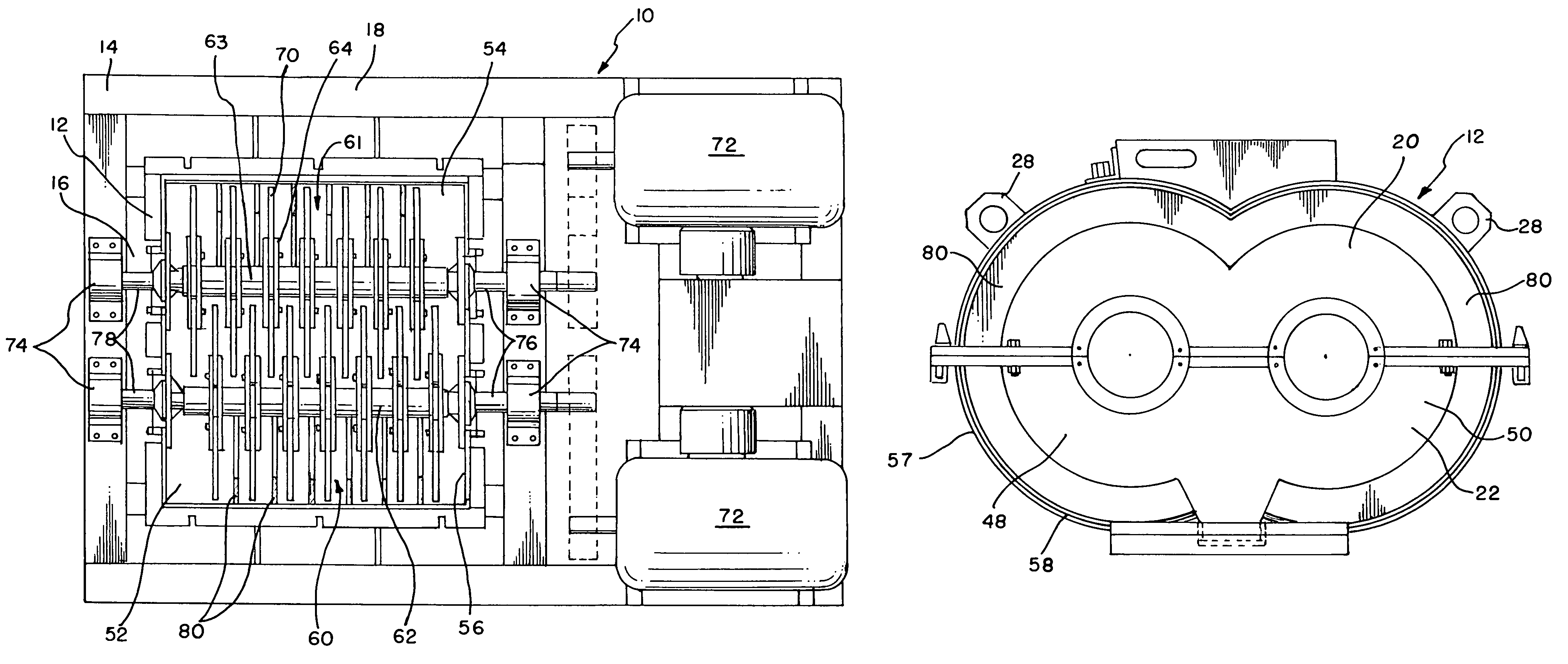
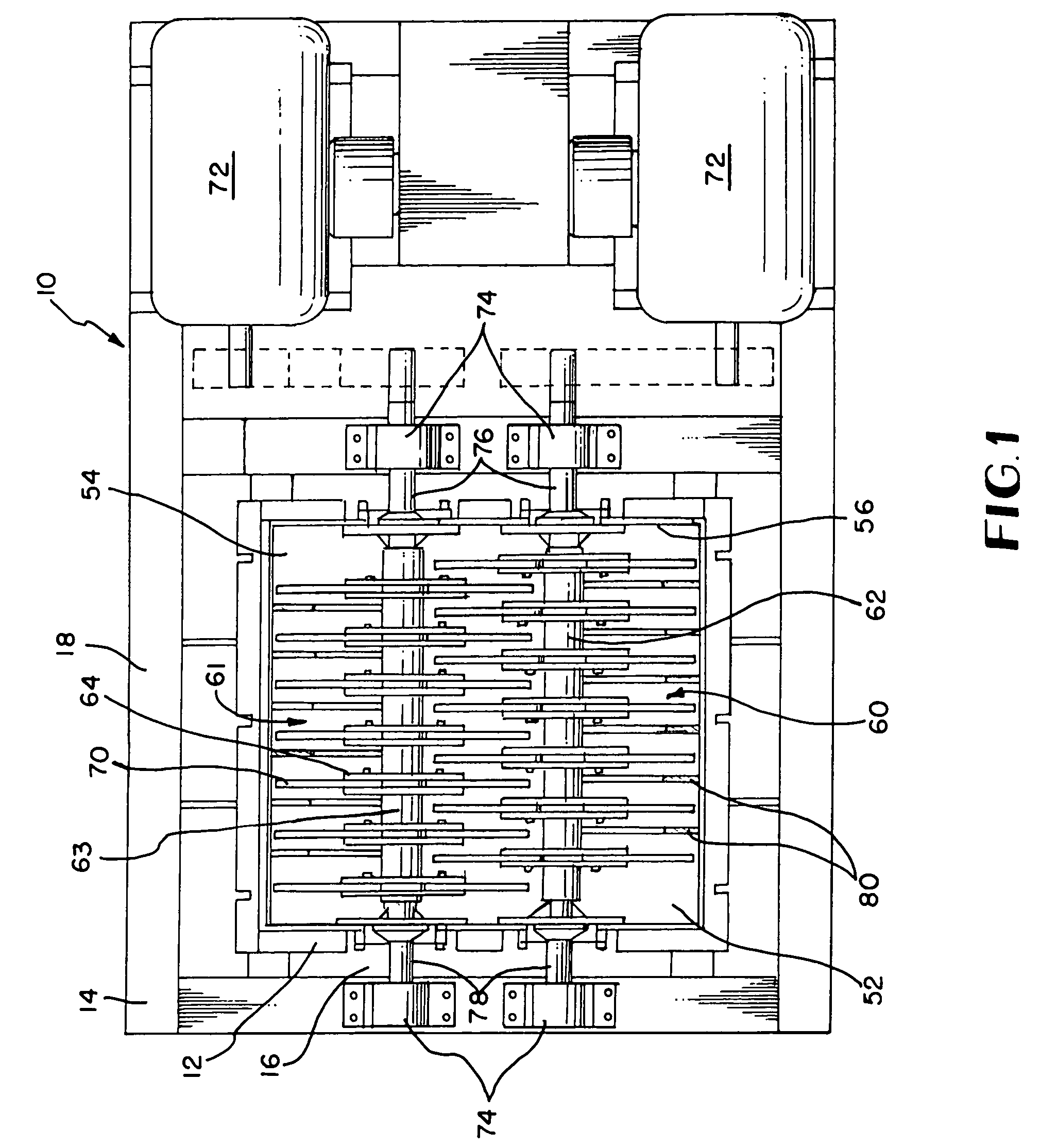
[0009]In the drawings, there is provided a material collider generally indicated by the numeral 10 including a housing assembly 12 securely mounted to a base frame assembly 14. The housing 12 and base frame 14 assemblies may be formed of structural steel, for example, and the housing assembly 12 is secured to the base frame assembly 14 so as to rest partially within a cavity 16 in the base frame assembly 14. The base frame assembly 14 is provided with support beams 18 which are at least eighteen inches in height to provide balance and stability as well as to reduce vibration during operation of the collider.

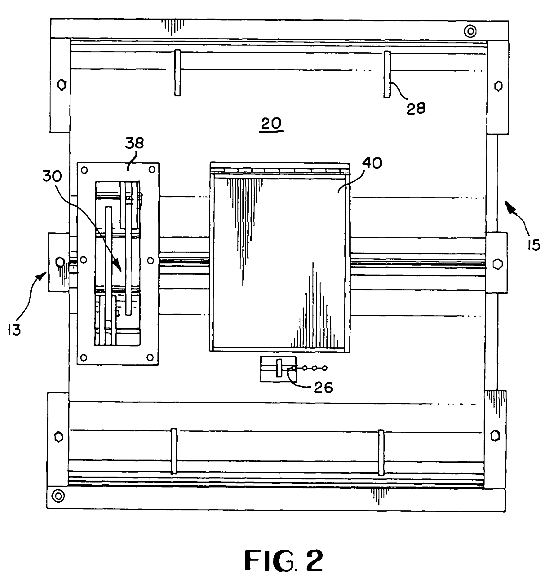
[0010]As shown in FIGS. 2 and 4, housing assembly 12 is formed of a two-piece construction, including a top section 20 and a bottom section 22 so as to allow the top section to be removed in circumstances requiring cleaning or replacing of components within the housing assembly 12. A sealing member 24 is positioned between top 20 and bottom 22 sections of the housing assembly and...


PUM


Abstract

A material collider having a pair of rotor assemblies respectively housed within a pair of interconnected cylindrical chambers with a plurality of disc members secured thereto, at least one thrust guide secured to the disc members and a weir secured to the inner periphery of the cylindrical chambers.

Description

BACKGROUND OF THE INVENTION[0001]The present invention is related to a material collider and more particularly to a material collider apparatus which can break down materials received into the apparatus, such as drill cuttings from a wellbore, to a reduced particle size for further use such as by reinjection of the refined cuttings down a wellbore. Drill cuttings are an inevitable by-product of well drilling and their disposal has been a longstanding problem. Offshore drilling operations, in particular, are problematic because of the need to transport the cuttings to a landfill or a shore-based processing system.[0002]Depending on the results required of a particular collider application, particle size variations are often necessary. In order to adjust the particle size of the solids that are discharged from the collider, a variation in flow speed or retention time in the collider is required. The amount of time that solids are retained within the collider determines the particle si...

Claims


Application Information

Patent Timeline
Patent Type & Authority Patents(United States)
IPC IPC(8): B02C13/20B02C1/10B02C13/00B02C13/282
CPCB02C13/282B02C13/20
Inventor PIERCE, MELVIN E.
Owner BISHOP DEBORAH PIERCE
Why Eureka
Try Eureka