Periscopic optical training system for operators of vehicles

Inactive Publication Date: 2006-06-06
LSA INC
View PDF43 Cites 20 Cited by
  • Summary
  • Abstract
  • Description
  • Claims
  • Application Information

AI Technical Summary

Benefits of technology

[0011]It is an object of the present invention to provide periscopic optical training for operators of vehicles or other apparatus that are equipped with a periscope sighting device that has the properties of allowing both a real field of view and a training field of view to be presented to the operator.
[0012]It is another object of the present invention to provide a compact optical display arrangement that uses a non-mechanical method to allow multiple images to be combined in a periscopic sighting device where each image can be selectively displayed or merged depending on the operator's needs.
[0014]It is a further object of the present invention to provide simultaneous operation of multiple training fields of view that when presented through the multiple periscopic sighting devices provide a large field of view without blind spots up to and including 360 degrees total coverage so that the operator is immersed in a panoramic surround.
[0016]It is a further object of the present invention to synthetically generate dynamic scenes as prepared by a video processing computer that can extract the salient features of the surrounding environment and synthesize engagement scenario simulations which are presented to the user / trainee as realistic in both temporal and visual sensation to an extent which closely simulates the real world outside of the apparatus so that practical and changeable engagement scenarios can be undergone by the user to his advantage for the accumulation of realistic training experience without loss of life, or limb or encounter with other dangerous environments.
[0017]It is a further object of the present invention to reduce the data rate of the dynamic scenes so that images can be digitally transmitted through slip rings and other data rate limiting junctures to provide real-time seamless spanning of multiple periscopic sighting devices.

Problems solved by technology

Many of the periscopic optical training vehicles, such as a tank or a submarine, do not have an open field of view thus periscopic devices permit a limited view of the external environment.
Such periscopic devices have to survive environmental (particularly shock and vibration) challenges.

Method used


Image

  • Periscopic optical training system for operators of vehicles
  • Periscopic optical training system for operators of vehicles
  • Periscopic optical training system for operators of vehicles

Examples


Embodiment Construction

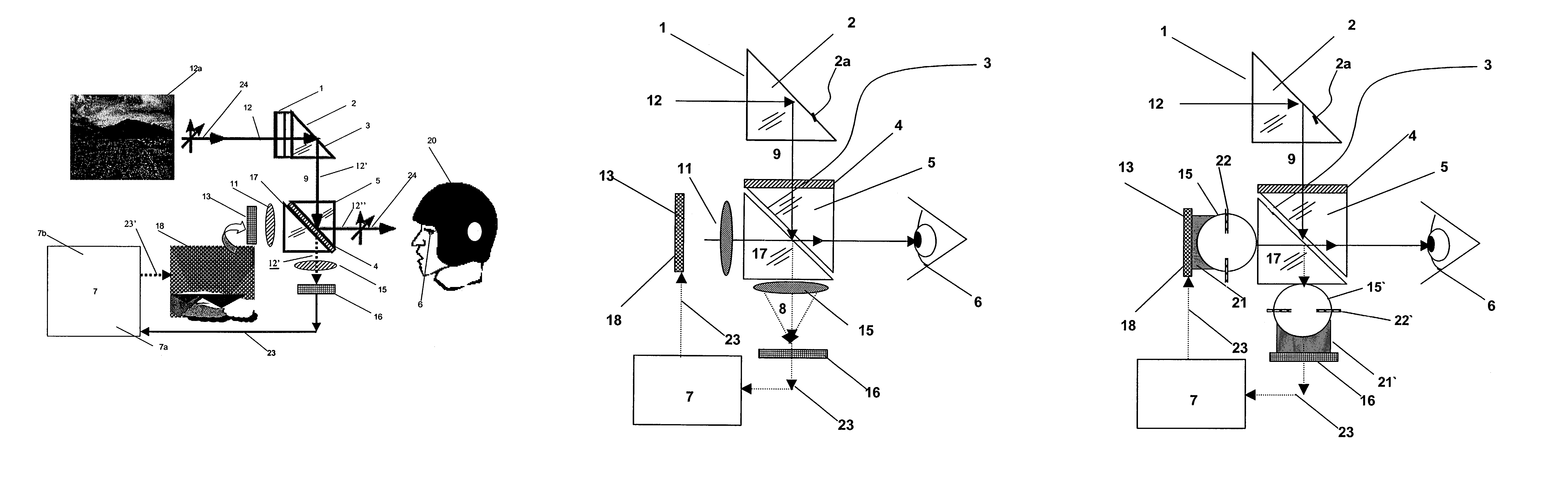
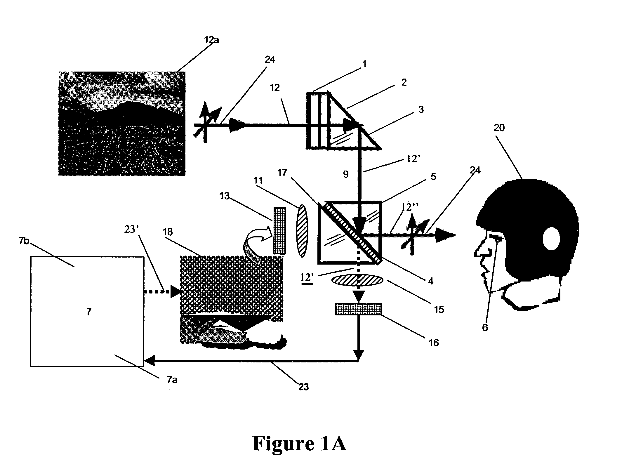
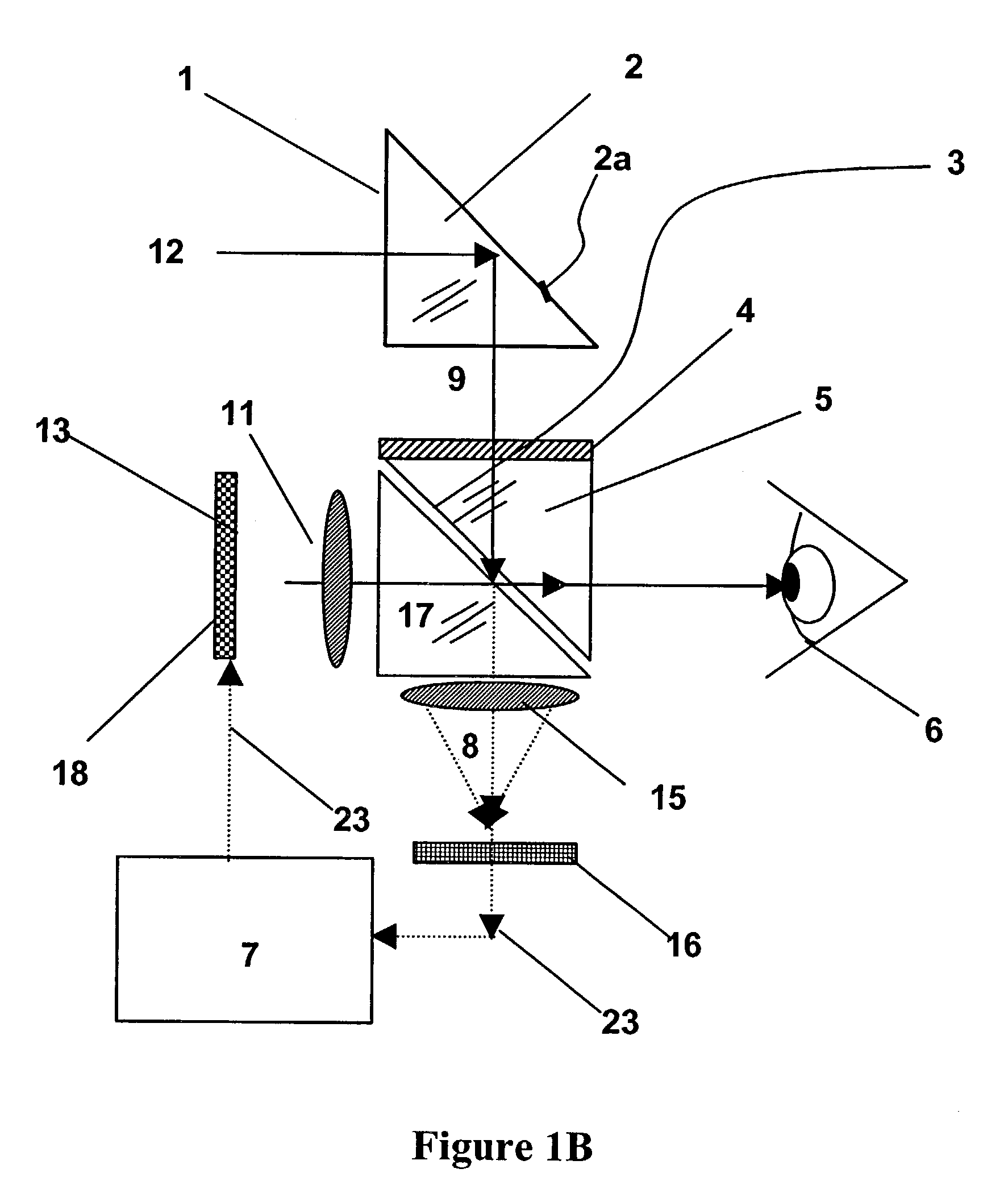
[0035]FIG. 1A is a schematic diagram of the system, a user 20 and the relationship therebetween. The system includes periscopic optics, a microprocessor 7, and an image display device 13, and periscopic optics. The periscopic optics include an entrance window face 1, a periscopic fold prism 2, a liquid crystal light control device 4, a periscopic fold prism 5, a block relay prism 17, which directs the collimated image light through the periscopic fold prism 5 by means of passing through the liquid crystal light control device 4, which contols its passage and superposition on the incoming collimated scene light as seen by the user 20. Each of the prisms 2, 5, 17 has a wedge shape with at least one right-angled triangular end face and three side faces connecting three sides of the end face. The three side faces include a hypotenuse side face connecting a hypotenuse side of the end face and two edge side faces each connecting one of the two remaining sides of the end face. Two of the p...


PUM


Abstract

A periscopic optical training system for displaying simulation and real images includes a microprocessor for generating at least one simulation image, at least one display for displaying the simulation image, at least one periscopic device each with a viewing window for receiving the simulation and real images, and a controller for controlling the simulation and real images to be received by the periscopic device interchangeably or simultaneously.

Description

[0001]This application claims the benefit of U.S. Provisional Patent Application Ser. No. 60 / 333,754 filed on Nov. 29, 2001, the entire disclosures of which are incorporated herein by reference.BACKGROUND OF THE INVENTION[0002]1. Field of the Invention[0003]The invention generally relates to a periscopic optical training system which displays simulation and real images, and a method for using the same. More particularly, it relates to an augmenting electro-optical periscopic in situ training system including an improved periscope and a computation-driven display which shows simulation and real images interchangeably or simultaneously.[0004]2. Description of Related Arts[0005]Proper training is essential for military forces around the world for teaching basic skills to new personnel and sustaining demanding skills that can degrade without practice. Different training methods have been employed in the form of various algorithms to synthesize real world scenario simulations, so that th...

Claims


Application Information

Patent Timeline
Patent Type & Authority Patents(United States)
IPC IPC(8): G09B9/00G09B19/16G09B9/08G02B27/01G09B9/24
CPCG02B23/08F41H5/266G09B9/245G02B27/0101
Inventor CABATO, ALVIN B.WARNER, DAVIDTYCZKA, DALE R.LEHMAN, JR., JOHN G.
Owner LSA INC
Why Eureka
Try Eureka