Method and apparatus for flushing contaminants from a container of fluids

Inactive Publication Date: 2006-06-06
HANSEN DENNIS B
View PDF34 Cites 13 Cited by
  • Summary
  • Abstract
  • Description
  • Claims
  • Application Information

AI Technical Summary

Benefits of technology

[0007]It is an advantage of the present invention to reduce the time consumed and complexity involved in reversing a flow direction during the flushing process.
[0008]It is another object of the present invention to provide for increased in-field utilization of a flushing system.
[0009]It is another feature of the present invention to include a fluid aeration mechanism with micro-bursts of air.
[0010]It is another advantage of the present invention to provide for a reduced overall time required to perform the flushing operation and thereby increase the overall in field utilization of the flushing equipment of the present invention.
[0011]It is yet another advantage of the present invention to greatly reduce oil misti

Problems solved by technology

Such systems frequently contain tiny metal shavings resulting from wear of internal parts.
However, these systems have had several drawbacks.
These systems can often take an extended period of time to maximize the removal of contaminants and sediment.
This

Method used


Image

  • Method and apparatus for flushing contaminants from a container of fluids
  • Method and apparatus for flushing contaminants from a container of fluids
  • Method and apparatus for flushing contaminants from a container of fluids

Examples


Example

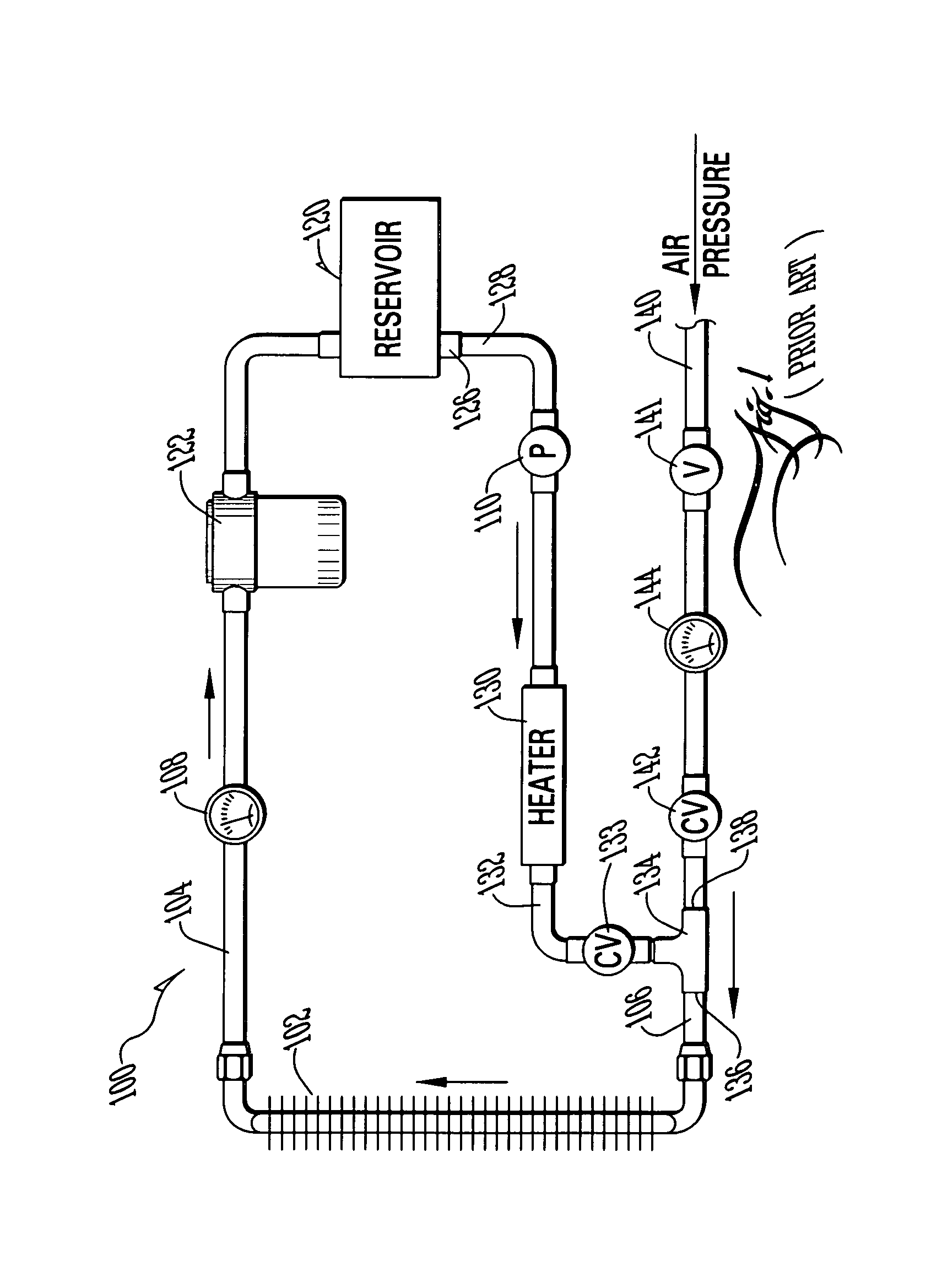
[0021]Now referring to the drawings, wherein like numerals refer to like matter throughout, and more particularly toFIG. 1, there is shown a simplified diagram of a prior art contaminant-flushing machine, generally designated 100, which is coupled to an automobile transmission cooler 102 by connecting hoses 104 and 106. Hoses 104 and 106 may be special heat-resistant hoses or other types. Additionally, hoses may be replaced with pipes (flexible or not), tubes, or any structure capable of carrying fluid under pressure. Hose 104 is coupled to temperature gauge 108. Also shown is a reservoir 120 which receives transmission fluid from line 104 by first passing such fluid through filter 122. Transmission fluid is disposed in the reservoir which will be extracted through port 126 and line 128 by pump 110. As the transmission fluid is pumped through pump 110 and on to heater 130, it is pressurized and heated to predetermined levels. Exiting from heater 130 is line 132, which is coupled thr...


PUM

PropertyMeasurementUnit
Fractionaaaaaaaaaa
Timeaaaaaaaaaa
Timeaaaaaaaaaa

Abstract

A contaminant-flushing machine for removing contaminants from a container, such as an engine transmission, air-conditioner coil, or transmission cooler, which includes hoses for coupling to the transmission cooler and a pump for circulating fluid through the hoses and the transmission cooler, and a fluid filter having a reduced tendency towards causing vaporization of the fluid. Also included in the contaminant-flushing machine is an automatic aeration system for injecting air into the circulating fluid at predetermined intervals. Additionally, a reverse flow piping circuit is included to permit automatic and electric manipulation of the flow direction of fluid through said transmission cooler while at the same time not altering the direction of flow of fluid through the pump. The flow reversals are repeated with a cycle of three (3) seconds in one direction followed by a flow in the other direction of one-fourth (¼) of a second, thereby creating an overall flow of fluid primarily in one reverse direction. The bursts of air are less than one (1) second and occur at five (5) second intervals.

Description

BACKGROUND OF INVENTION[0001]The present invention generally relates to fluid filtering, and more particularly relates to a method and apparatus for removing contaminants from a container having petroleum-based fluids therein, through a process of circulating, heating and filtering such fluids outside of the container.[0002]In the past, automotive engineers and technicians have been among the many people to recognize the need for an ability to flush contaminants from fluid-containing enclosures or systems. One example of such a fluid-containing system is a transmission / transmission cooler system in which transmission fluid therein is normally cooled during operation of a vehicle by passing the transmission fluid through the transmission cooler. Such systems frequently contain tiny metal shavings resulting from wear of internal parts. It is desirable to provide an effective way to remove such metal shavings and other contaminants from the system without the need for completely disman...

Claims


Application Information

Patent Timeline
IPC IPC(8): B01D37/00F01P11/06
CPCF01P11/06F01P2060/045F01P2011/065
Inventor HANSEN, DENNIS B.
Owner HANSEN DENNIS B
Why Eureka
Try Eureka