Induction heating device

Inactive Publication Date: 2006-06-06
PANASONIC CORP
View PDF16 Cites 19 Cited by
  • Summary
  • Abstract
  • Description
  • Claims
  • Application Information

AI Technical Summary

Benefits of technology

[0065]In the invention in accordance with an embodiment, a plurality of electrical conductor temperature sensors are provided; when the highest detection temperature among their plural detection temperatures becomes a predetermined temperature or more, the output of the drive circuit for supplying a high-frequency current to the above-mentioned heating coil is decreased, and the temperature of the electrical conductor is lowered. In a state wherein the heat of the electrical conductor cannot be dissipated to the object to be heated because of the dislocation or the like of the object to be heated, the electrical conductor becomes a high temperature locally; however, since the output is controlled by using the detection output of the electrical conductor temperature sensor that detects the temperature of the local area having the high temperature, the overheating of the electrical conductor is prevented, and the components and the like in the vicinity of the electrical conductor are hardly susceptible to thermal damage and the like.
[0066]In the invention in accordance with an embodiment, when the temperature difference among the detection temperatures of the plurality of electrical conductor temperature sensors becomes a predetermined value or more, the output of the drive circuit for supplying a high-frequency current to the above-mentioned heating coil is decreased. If the object to be heated is dislocated from its proper position on the plate or if one side of the object to be heated is floated, the heat dissipation at the portion (separated portion) of the electrical conductor away from the object to be heated becomes worse, and the temperature rises significantly. As a result, the temperature of the electrical conductor temperature sensor in the vicinity of the separated portion rises. The temperature of the electrical conductor temperature sensor in the vicinity of the portion of the plate on which the object to be heated is present is kept at the predetermined temperature, since the heat dissipation from the electrical conductor to the object to be heated is maintained. As described above, when the temperatures of the electrical conductor differ locally, by detecting the temperature difference, abnormality can be detected promptly. Hence, the heat-resistant levels of the components in the vicinity of the electrical conductor can be lowered. In addition, the temperature of the portion of the plate, not making contact with the object to be heated, can be prevented from rising locally and abnormally.
[0067]In the invention in accordance with an embodiment, a heat insulator is provided on the bottom face of the electrical conductor, and the electrical conductor temperature sensors are made contact with the bottom face of the heat insulator. With this configuration, the heat of the electrical conductor is shut off to some extent by the heat insulator, whereby the adverse effect of the heat on the heating coil and the like is hardly given. Since the electrical conductor temperature sensors are made contact with the electrical conductor via the heat insulator, even if the heat-resistant temperature of the electrical conductor temperature sensors is low, a configuration conforming thereto can be obtained by adjusting the thickness and the like of the he

Problems solved by technology

However, since the electric power for heating is restricted, sufficient heating power is not obtained, thereby causing a problem of getting into a situation wherein cooking is interrupted in some cases.
Hence, the pan is floated, and it is difficult to heat at higher input power.
However, according to expe

Method used


Image

  • Induction heating device
  • Induction heating device
  • Induction heating device

Examples


first embodiment

[0095]A first embodiment of an induction heating apparatus in accordance with the present invention will be described referring to FIG. 1 to FIG. 7.

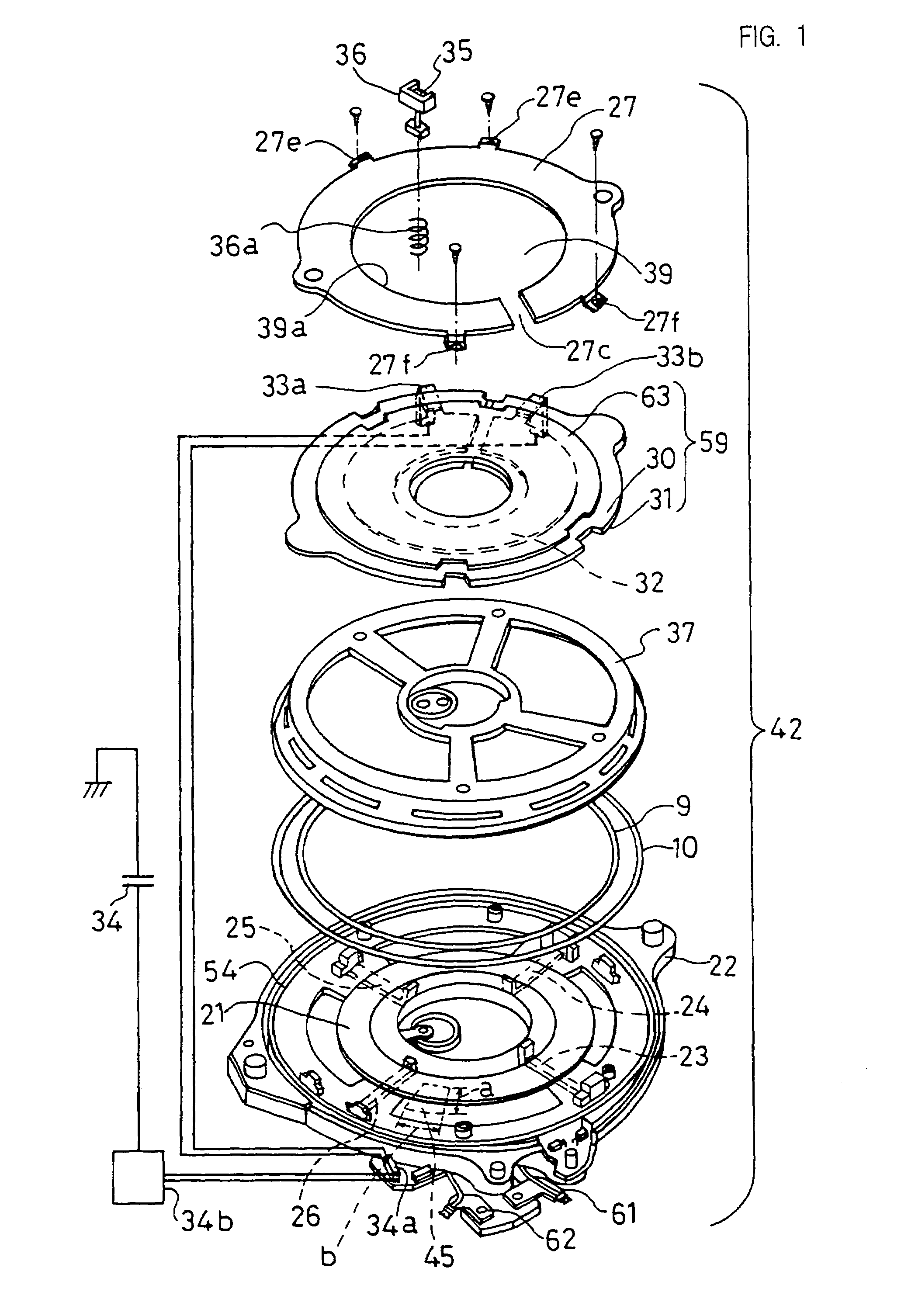
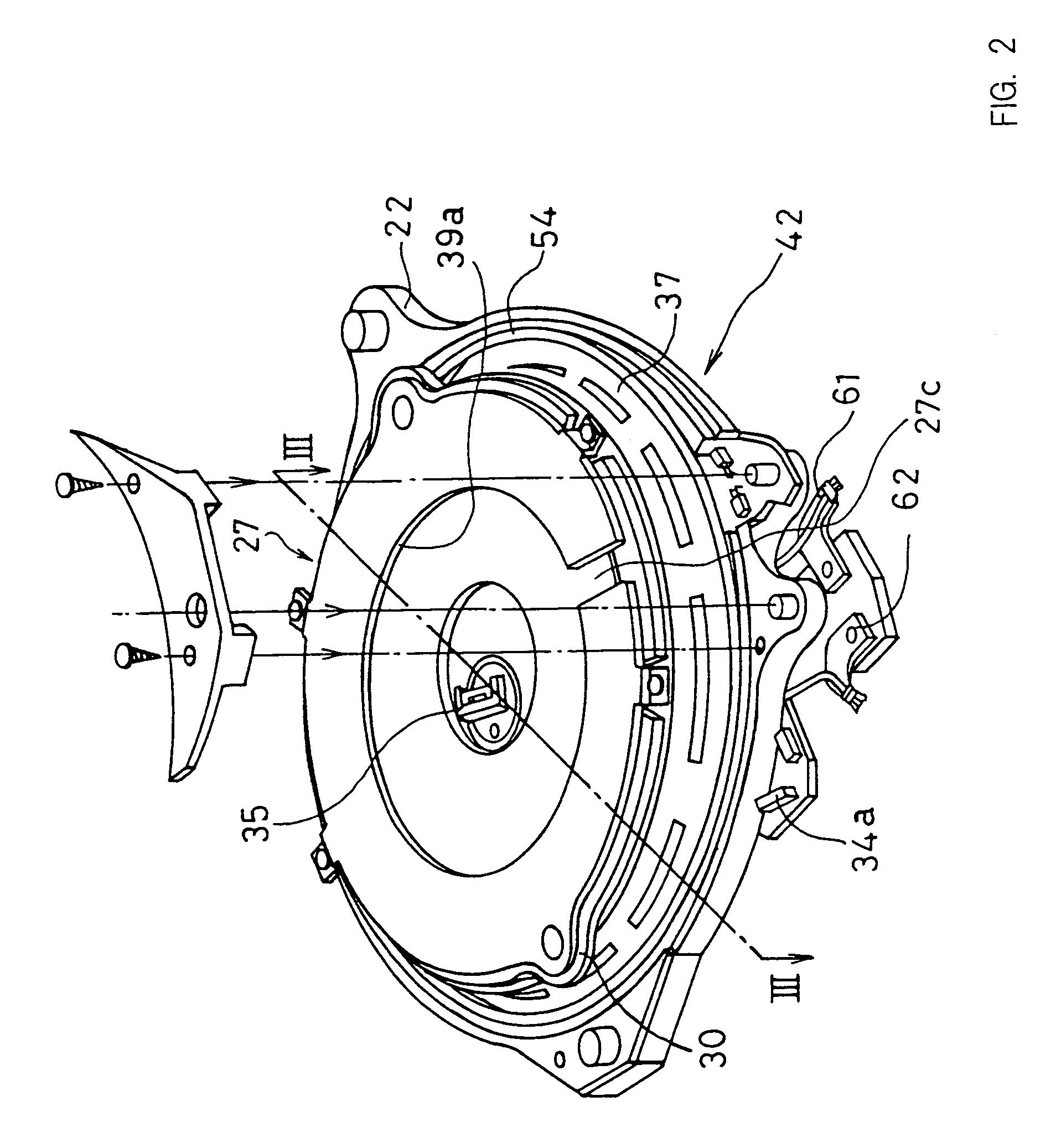
[0096]FIG. 1 is an exploded perspective view showing the configuration of an induction heating section 42 including a heating coil 21 in the induction heating apparatus (for example, an induction heating cooker) in accordance with the first embodiment of the present invention, and FIG. 2 is an assembled perspective view of the induction heating section 42. FIG. 3 is a cross-sectional view showing the induction heating section 42, a plate 28 secured to the upper portion of the main body of the induction heating cooker and an object 29 to be heated which is placed on the plate 28. The object 29 to be heated is made of aluminum, copper or a low magnetic permeability material having an electrical conductivity nearly equal to or higher than those of these.

[0097]In FIGS. 1, 2 and 3, first magnetic bodies, that is, ferrite cores 23, 24, 25 and ...

second embodiment

[0133]An induction heating apparatus in accordance with a second embodiment of the present invention will be described referring to FIG. 8. In this embodiment, an electrical conductor 77 shown in the plan view of FIG. 8 is provided instead of the electrical conductor 27 of the induction heating section 42 in accordance with the above-mentioned first embodiment as shown in FIG. 1 to FIG. 3. The other configurations are the same as those shown in FIGS. 1 to 3.

[0134]In FIG. 8, the electrical conductor 77 is preferably provided with four wedge-shaped notches 77a in an aluminum disc preferably having a thickness of 1 mm. By providing the notches 77a in the electrical conductor 77, the passage and direction of the induction current induced in the electrical conductor 77 by the magnetic field from the heating coil 21 are indicated by curve A. Broken line B indicates the passage and direction of the current flowing in the heating coil 21. Since no current is induced at the notches 77a, the ...

third embodiment

[0143]An induction heating apparatus in accordance with a third embodiment of the present invention will be described referring to FIG. 9. In this embodiment, an electrical conductor 80 shown in the plan view of FIG. 9 is provided instead of the electrical conductor 27 of the induction heating section 42 in accordance with the above-mentioned first embodiment shown in FIG. 1 to FIG. 3. The other configurations are the same as those shown in FIGS. 1 to FIG. 3. In FIG. 9, the electrical conductor 80 is formed by radially disposing a plurality (eight in FIG. 9) of conductor plates 80a, such as strip-shaped aluminum plates preferably having a thickness of about 1 mm, a width of about 10 mm and a length of about 70 mm. The conductor plates 80a are disposed on the heat-resistant sheet 63 shown in FIG. 1 while being electrically insulated from one another. Since the conductor plates 80a disposed radially are insulated from one another, no circulating current is generated in the electrical ...


PUM


Abstract

In an induction heating apparatus, in order to decrease the buoyancy exerted on an object to be heated which is made of a material having high electrical conductivity and low magnetic permeability, such as aluminum, an electrical conductor is provided between a heating coil and the object to be heated, thereby increasing the equivalent series resistance of the heating coil. Hence, the current of the heating coil, which is required for obtaining a desired heating output, is decreased, whereby the buoyancy of the object to be heated can be decreased. In addition, the electrical conductor is divided into two halves, and they are arranged in a circular arc form with a clearance provided therebetween and made close contact with the bottom face of a plate, whereby the temperature rise of the electrical conductor can be restricted. Furthermore, the heat of the electrical conductor is transferred and dissipated to the object to be heated, whereby the heating coil and the like are not damaged even if the electrical conductor is heated. An electrical conductor temperature sensor for detecting the temperature of the electrical conductor is provided; when the detection temperature becomes a predetermined temperature, the heating output of a drive circuit is decreased, whereby the heat generation of the electrical conductor is decreased and the heating coil and the like are not damaged by heat.

Description

TECHNICAL FIELD[0001]The present invention relates to an induction heating apparatus for use in general households, offices, restaurants, factories, etc. More in detail, the present invention relates to an induction heating cooker for heating an object to be heated which is made of a material having low magnetic permeability and high electrical conductivity, such as aluminum or copper, to an induction heating water heater, to an induction heating iron and to other heating apparatuses of induction heating method.BACKGROUND ART[0002]A conventional and general induction heating apparatus, such as an induction heating cooker, will be described referring to FIG. 20 to FIG. 22.[0003]FIG. 20 is a cross-sectional view of a conventional induction heating cooker. In the figure, a pan or an object 1 to be heated having the shape of the pan is placed on a plate 4 provided above an induction heating section 3 having a heating coil 2. The plate 4 is, for example, an insulation plate made of a cer...

Claims


Application Information

Patent Timeline
IPC IPC(8): H05B6/12H05B6/32
CPCH05B6/1254Y02B40/126H05B2206/022Y02B40/00H05B6/04H05B6/12
Inventor HIROTA, IZUOFUJITA, ATSUSHIMIYAUCHI, TAKAHIROFUJII, YUJIKATAOKA, AKIRAAIHARA, KATSUYUKIMAKIO, NOBUYOSHI
Owner PANASONIC CORP
Why Eureka
Try Eureka