
Electrical wiring inspection system

a technology of electrical wiring and inspection system, applied in the direction of impedence measurement, measurement using digital techniques, instruments, etc., can solve the problem of more dangerous faulty electrical wiring, and achieve the effect of simplifying the presentation

Inactive Publication Date: 2006-06-06
BLADES FREDERICK K
View PDF10 Cites 93 Cited by
  • Summary
  • Abstract
  • Description
  • Claims
  • Application Information

AI Technical Summary

Benefits of technology

"The present invention is a modular diagnostic instrument called the SafeWire™ system, which allows an electrician to quickly and easily test every electrical wire, connection, outlet, switch, and appliance in a house. The system includes a portable circuit analyzer (PCA) that is connected to the building's load center and a handheld computer device with custom software. The electrician uses the PCA to test each circuit in the house, recording the results on the handheld device. The system can generate a complete schematic diagram of the house, including the identification of each circuit's branch and the load or connection point it is connected to. The SafeWire™ system can be used for testing single-family residences, duplex homes, apartment buildings, office buildings, and other structures that use electrical distribution systems. It can also be adapted for testing 3-phase power distribution systems. The disclosure of the use of the SafeWire™ system to test residential wiring is provided for the purpose of explaining a complex system, and it can be used in various countries with different electrical standards."

Problems solved by technology

Indeed SafeWire™ testing may prove more valuable elsewhere in the world where a combination of higher line voltages, older structures and perhaps less rigorous electrical standards may make faulty electrical wiring more dangerous.

Method used


Image

  • Electrical wiring inspection system
  • Electrical wiring inspection system
  • Electrical wiring inspection system

Examples


Embodiment Construction

1. Overview of the Safe Wire™ System

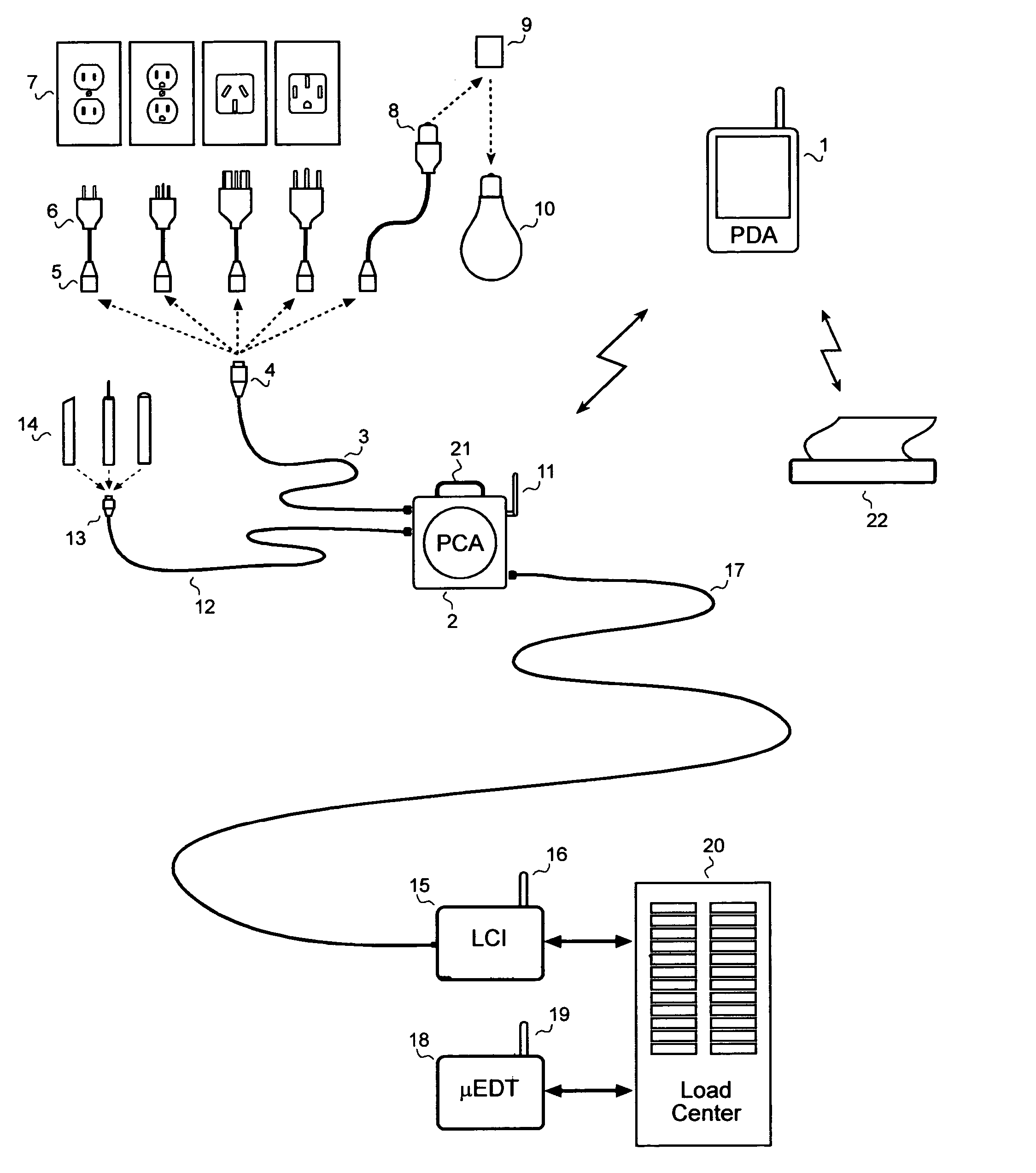
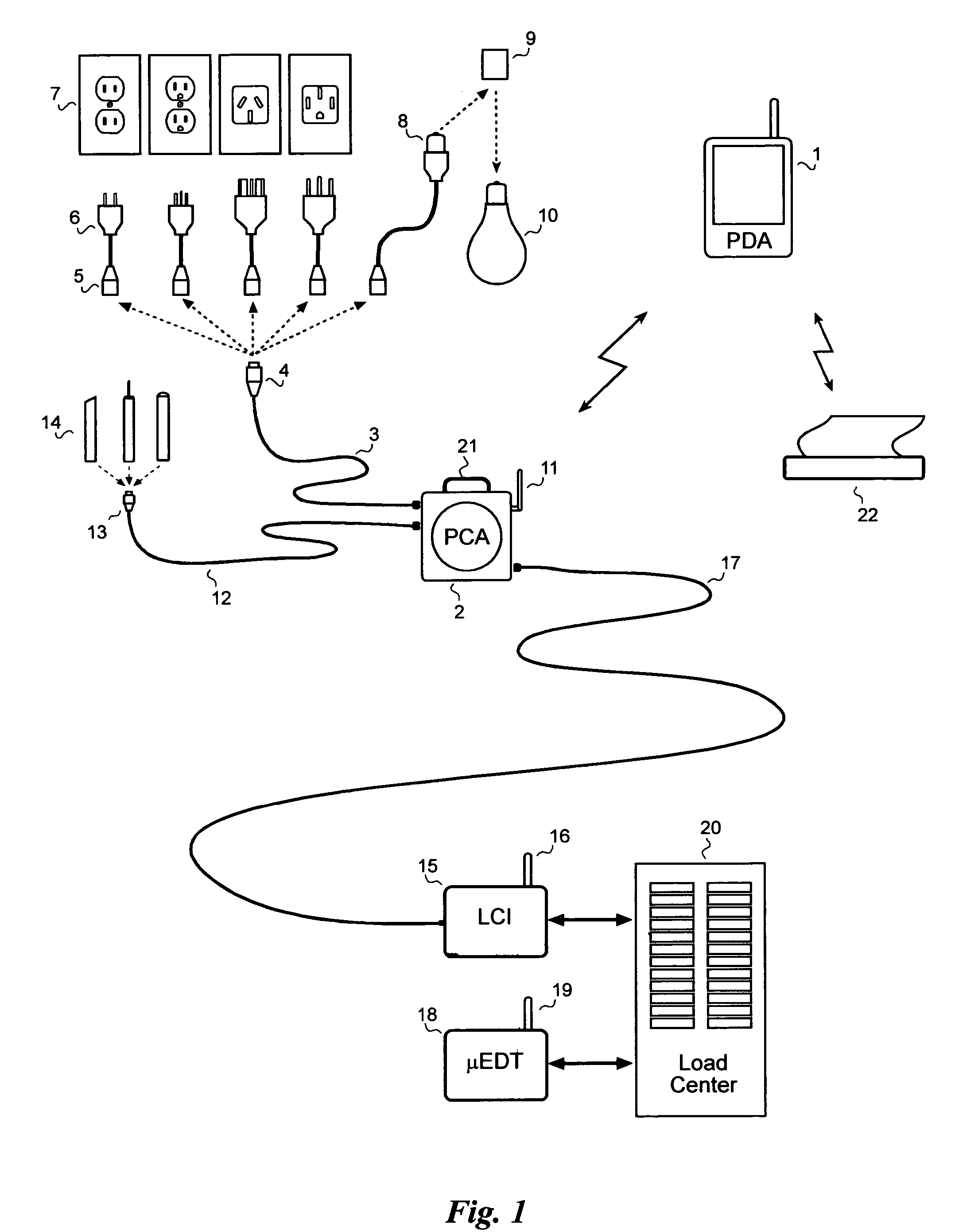
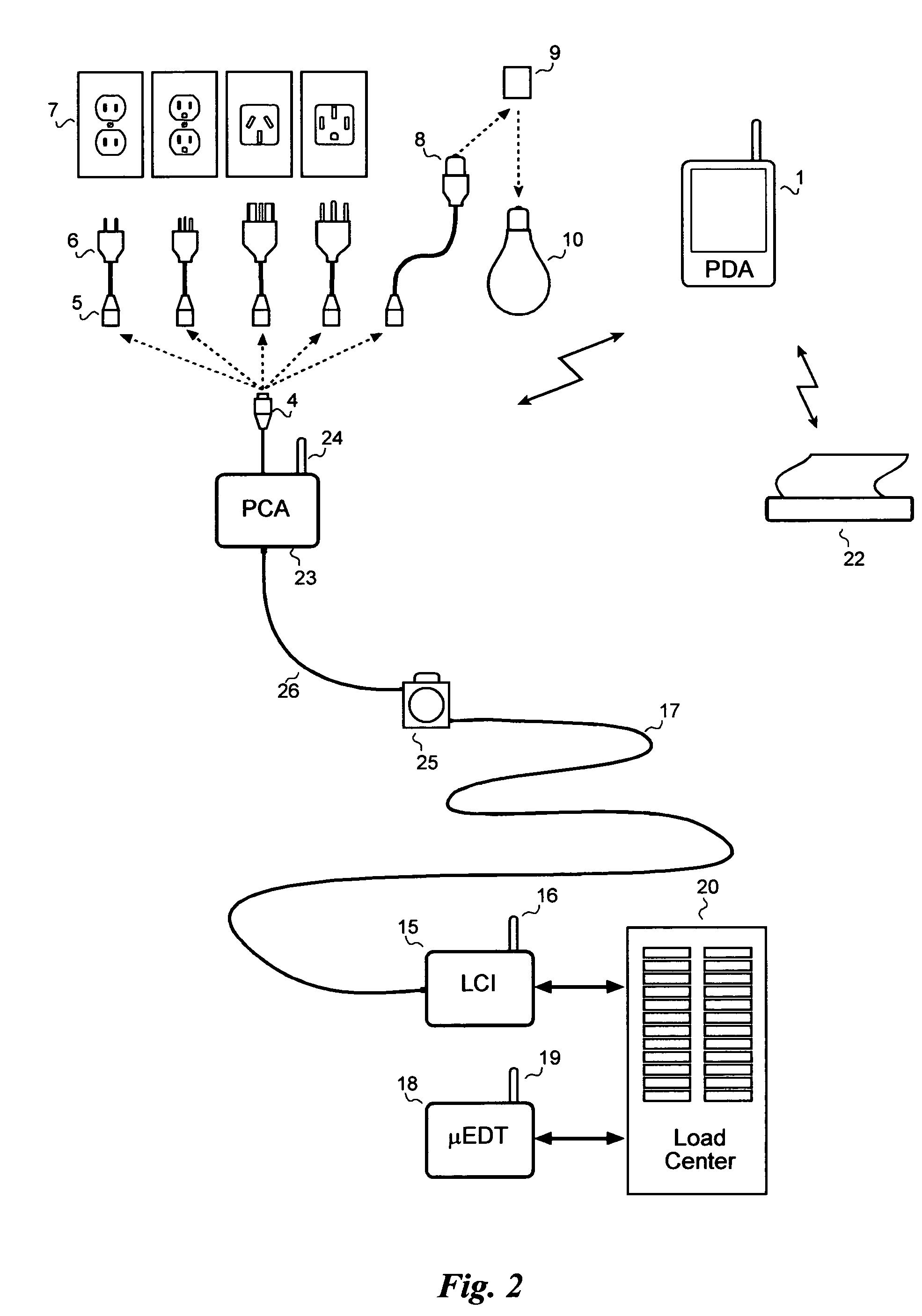
[0059]The preferred embodiment of the SafeWire™ System of the invention is shown in simplified physical form in FIG. 1. The system is made up of four basic components that work together to enable a single electrician to take extensive measurements on a household wiring system in a convenient manner and in a relatively short period of time.

[0060]An off-the-shelf handheld computer 1, commonly known as a Personal Digital Assistant (PDA), provides the computing power and a user interface for the SafeWire™ system. Custom SafeWire™ software runs in the PDA and the electrician uses it to control and review all aspects of the SafeWire™ system. In the preferred embodiment of the present invention, the PDA 1 is one of several commercially-available PDAs with integral radio communication capabilities, such as Bluetooth, to wirelessly communicate with the other SafeWire™ components. Provision of wireless communication (as opposed to a wired connection) enable...


PUM


Abstract

A system for testing and documenting the electrical wiring in a building, for example, includes a Portable Circuit Analyzer (PCA) that is connected to the building's Load Center through an umbilical cord. The PCA is in wireless communication with a hand-held computer device, such as a personal digital assistant (PDA) as now widely available, provided with custom software according to the invention. The electrician connects the PCA in succession to each circuit in the building, operating each switch, and each fixture or appliance, while recording the test results of the circuit element on the PDA. The PCA measures the resistance and length of each circuit thus established. When the test process is completed, the PDA is enabled to generate a complete schematic diagram of the building, including, for example, an identification of the branch circuit to which each fixture, outlet, appliance, or other load or connection point is connected.

Description

CROSS-REFERENCE TO RELATED APPLICATION[0001]This application claims priority from provisional application Ser. No. 60 / 555,331, filed Mar. 23, 2004.FIELD OF THE INVENTION[0002]This application relates to electrical test equipment for testing the integrity of electrical power distribution systems and for locating faults in the same.[0003]Essentially all aspects of the present invention except the Electromagnetic Wire Locating method disclosed in Section 7 were disclosed in the Provisional Application listed.BACKGROUND OF THE INVENTION[0004]Residential dwellings, office buildings and businesses in the United States are typically wired in accordance with the National Electrical Code, inspected after initial construction, and then never again tested unless a problem occurs. Yet, after 10, 20, or 30 years of continuous use, wire insulation dries out and cracks, contacts become loose, light sockets degrade from heat, switches lose their spring, and numerous other aging processes take their...

Claims


Application Information

Patent Timeline
Patent Type & Authority Patents(United States)
IPC IPC(8): G01R27/08G01R19/00G01R19/25G01R27/16G01R31/58
CPCG01R31/041G01R31/02G01R19/2513G01R19/2516G01R27/16G01R31/086G01R31/026G01R1/025G01R31/67G01R31/54G01R31/58
Inventor BLADES, FREDERICK K.
Owner BLADES FREDERICK K
Learn More