Liquid crystal display with neutral dark state

a liquid crystal display and neutral dark state technology, applied in the field of optical displays, can solve the problems introducing undesirable color shift, reducing image contrast, etc., and achieves the effect of reducing the useful viewing angle of the display, improving the type of polarizer, and reducing thickness

Inactive Publication Date: 2006-06-06
SEIKO EPSON CORP
View PDF12 Cites 30 Cited by
  • Summary
  • Abstract
  • Description
  • Claims
  • Application Information

AI Technical Summary

Benefits of technology

[0007]The requirement for H-type polarizers to include protective cladding layers adds thickness to a liquid crystal display. In some situations, the cladding layers also display an undesirable type of birefringence that results in the dark state of the display becoming colored, and also results in a reduction of the useful viewing angle of the display. There is a need, therefore, to improve the type of polarizer used with certain LCD displays, so as to reduce the thickness, to make the color of the dark state more neutral, and to maintain the large viewing angle of the display.
[0008]The present invention is directed to the use of a polarizer with a liquid crystal display (LCD) cell whose liquid crystal molecules are switched in the plane of the cell (switched-in-plane: SIP). The SIP LCD has birefringent properties tat are different from other types of LCD cell. Consequently, the use of an absorbing polarizer that introduces birefringence with a SIP LCD reduces the image contrast and introduces an undesirable color shift. The use of a low birefringence polarizer with the SIP LCD cell maintains image contrast and does not introduce a color shift.

Problems solved by technology

In some situations, the cladding layers also display an undesirable type of birefringence that results in the dark state of the display becoming colored, and also results in a reduction of the useful viewing angle of the display.
Consequently, the use of an absorbing polarizer that introduces birefringence with a SIP LCD reduces the image contrast and introduces an undesirable color shift.

Method used


Image

  • Liquid crystal display with neutral dark state
  • Liquid crystal display with neutral dark state
  • Liquid crystal display with neutral dark state

Examples


Embodiment Construction

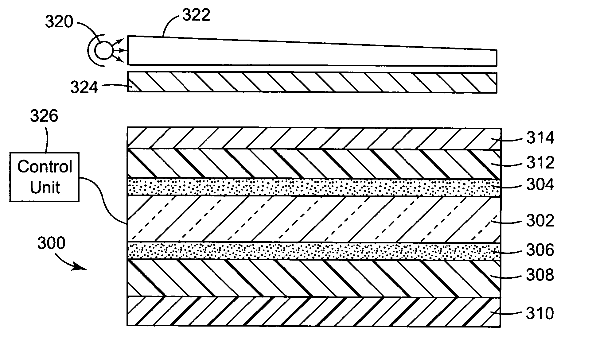
[0022]The present invention is applicable to liquid crystal displays (LCDs), and is particularly applicable to LCDs whose liquid crystals are switched in the plane of the display. The use of an absorbing polarizer that has reduced birefringence yields improved viewing angle and maintains color neutrality in the dark state compared to an LCD that uses absorbing polarizers that have TAC layers.

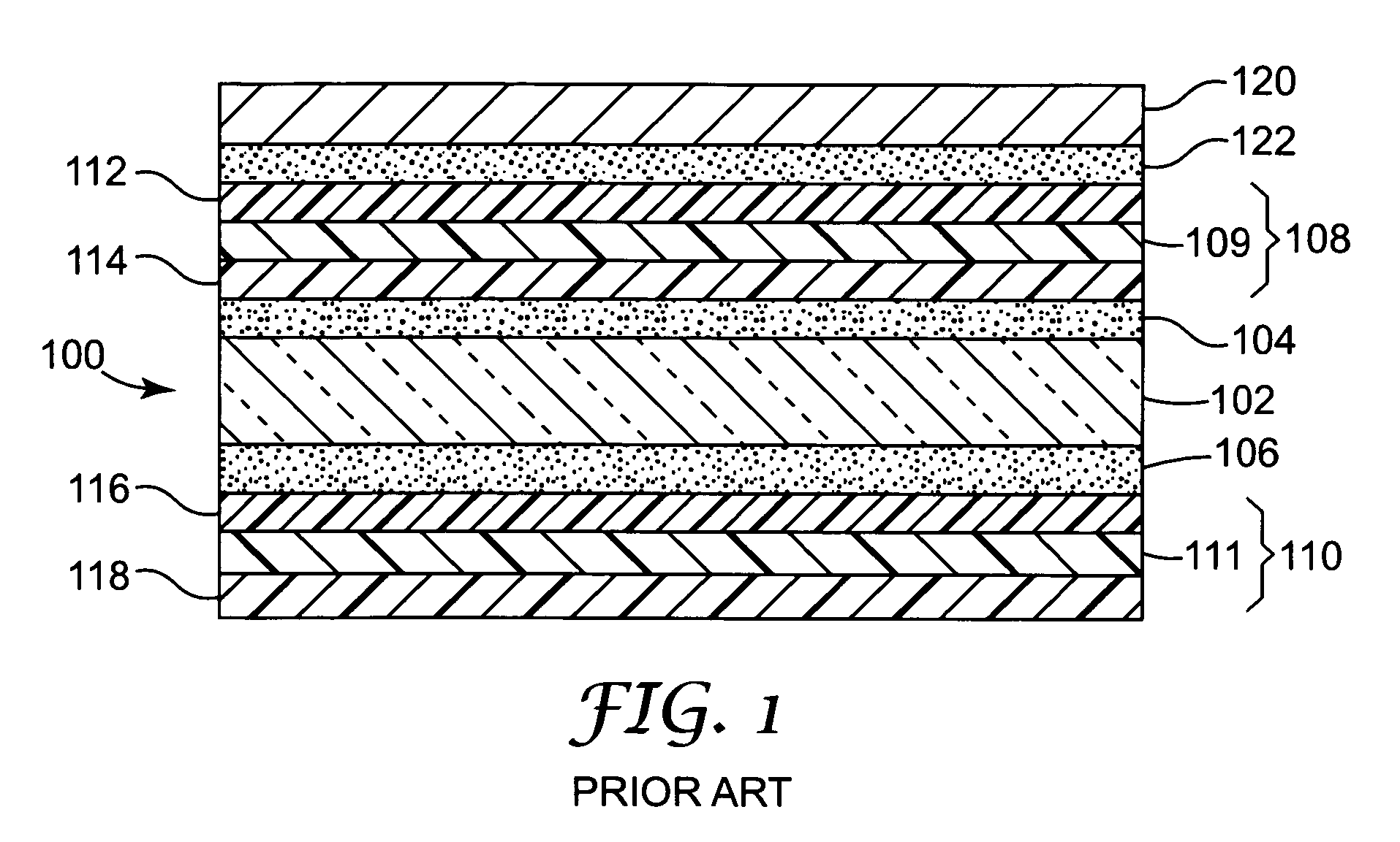
[0023]A conventional liquid crystal display (LCD) stack 100 that uses H-type polarizers is schematically shown in FIG. 1. A liquid crystal display cell 102 is typically formed of a liquid crystal (LC) layer sandwiched between two glass plates. The upper and lower surfaces of the LCD cell 102 are provided with layers 104, 106 of an adhesive, e.g., a pressure sensitive adhesive, to secure polarizer structures 108 and 110 to each surface of the liquid crystal display cell. The H-type polarizers 108 and 110 each include iodine-containing absorbing polarizer layers 109, 111, and also include layers 1...


PUM

PropertyMeasurementUnit
thicknessaaaaaaaaaa
thicknessaaaaaaaaaa
thicknessaaaaaaaaaa

Abstract

A polarizer is used with a liquid crystal display (LCD) cell whose liquid crystal molecules are switched in the plane of the cell. The LCD has birefringent properties that are different from other types of LCD cell and, unlike other types of LCD, the image contrast is maintained and there is little color shift in the dark state when a low birefringence polarizer is used with the SIP LCD cell. In one embodiment, the x-z retardation of the layers between the polarization-sensitive absorbing layer and the LCD is less than 20 nm. In another embodiment, the x-z birefringence is less than 0.0005. The low levels of retardation and birefringence may be achieved by omitting the commonly used cellulose triacetate layer between the polarization-sensitive absorbing layer and the LCD.

Description

FIELD OF THE INVENTION[0001]The invention relates to optical displays, and more particularly to an improved type of liquid crystal display used with a polarizer.BACKGROUND[0002]Liquid crystal displays (LCDs) are optical displays used in devices such as laptop computers, hand-held calculators and digital watches. A typical LCD includes an LCD layer and an electrode matrix, disposed between a pair of absorbing polarizers. For color displays, the LCD typically also includes a color filter. The optical state of portions of the LCD cell is altered by the application of an electric field using the electrode matrix. The combination of the altered optical state of the liquid crystals and the polarizers results in the appearance of pixels of polarized light on the liquid crystal display to form the desired image.[0003]A typical liquid crystal display includes a front polarizer, closer to the viewer, and a rear polarizer, on the other side of the LCD from the viewer. These polarizers are plan...

Claims


Application Information

Patent Timeline
Patent Type & Authority Patents(United States)
IPC IPC(8): G02F1/1335G02F1/1343G02B5/30G02F1/141
CPCG02F1/133528G02F1/134363G02F1/1335G02F1/13363
Inventor WATSON, PHILIP E.RALLI, PHILIP J.CAEL, JOHN J.
Owner SEIKO EPSON CORP
Why Eureka
Try Eureka