Device for the pixel-by-pixel photoelectric measurement of a planar measured object

a photoelectric measurement and object technology, applied in the field of pixel-by-pixel photoelectric measurement of a planar or flat, can solve the problems of less pronounced reflection image, spectral errors, and optical projection means that cannot be completely free of geometrical distortions

Active Publication Date: 2006-06-06
X RITE SWITZERLAND
View PDF3 Cites 13 Cited by
  • Summary
  • Abstract
  • Description
  • Claims
  • Application Information

AI Technical Summary

Benefits of technology

[0011]It is therefor a further important object of the present invention to provide means for correcting the mentioned interference effects so that the measured data have the precision required for calorimetric applications.
[0012]The solution of this further object of the invention is achieved by carrying out corrective measur

Problems solved by technology

It is a further problem of the calorimetric measurement by way of a video camera of large surface measured objects that on the one hand the optical projection means cannot be made completely free of geometrical distortions at reasonable cost and produce more or less pronounced reflection images and that on the other hand scattered or adventitious light effects occur between the

Method used


Image

  • Device for the pixel-by-pixel photoelectric measurement of a planar measured object
  • Device for the pixel-by-pixel photoelectric measurement of a planar measured object
  • Device for the pixel-by-pixel photoelectric measurement of a planar measured object

Examples


Embodiment Construction

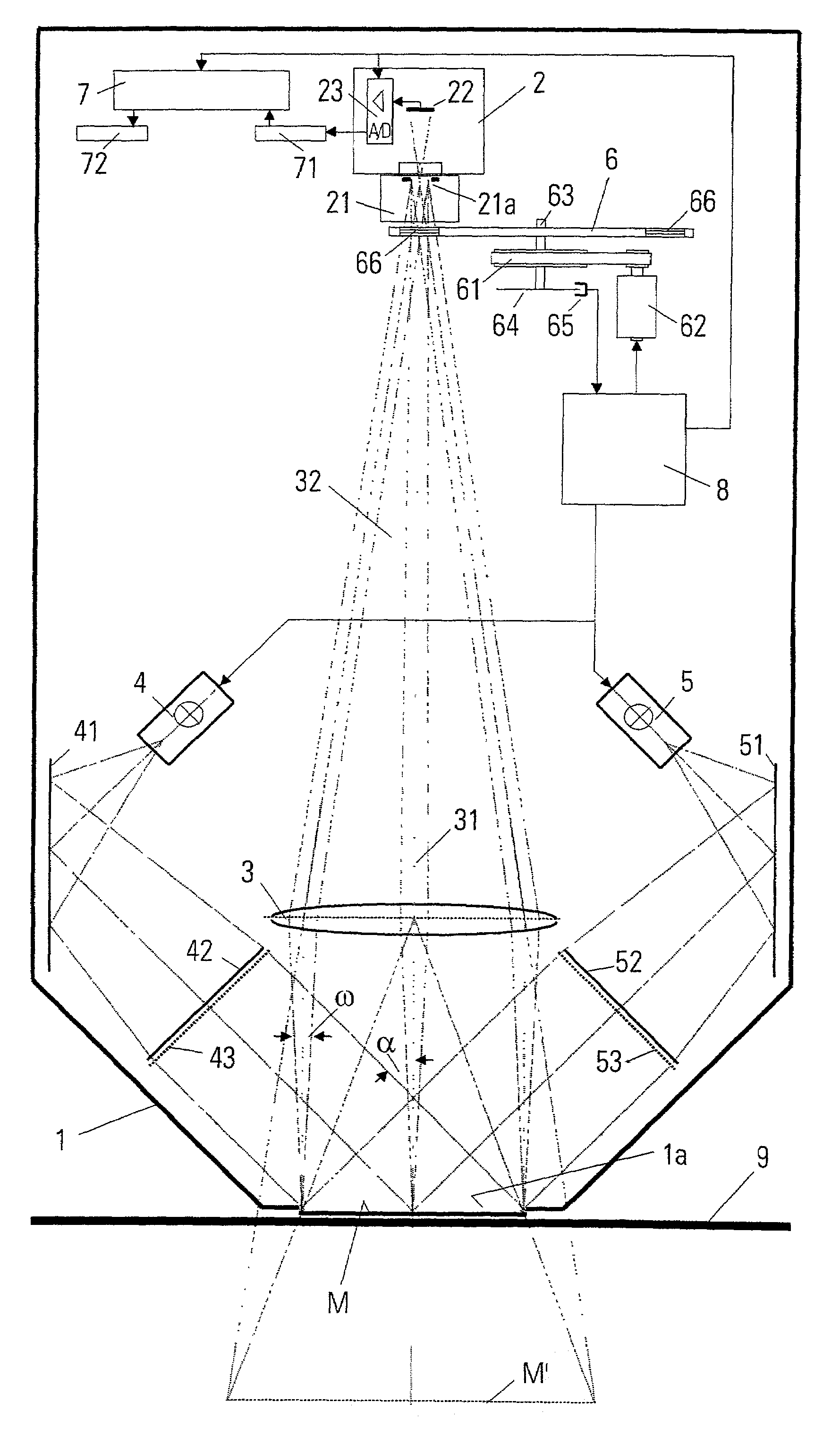
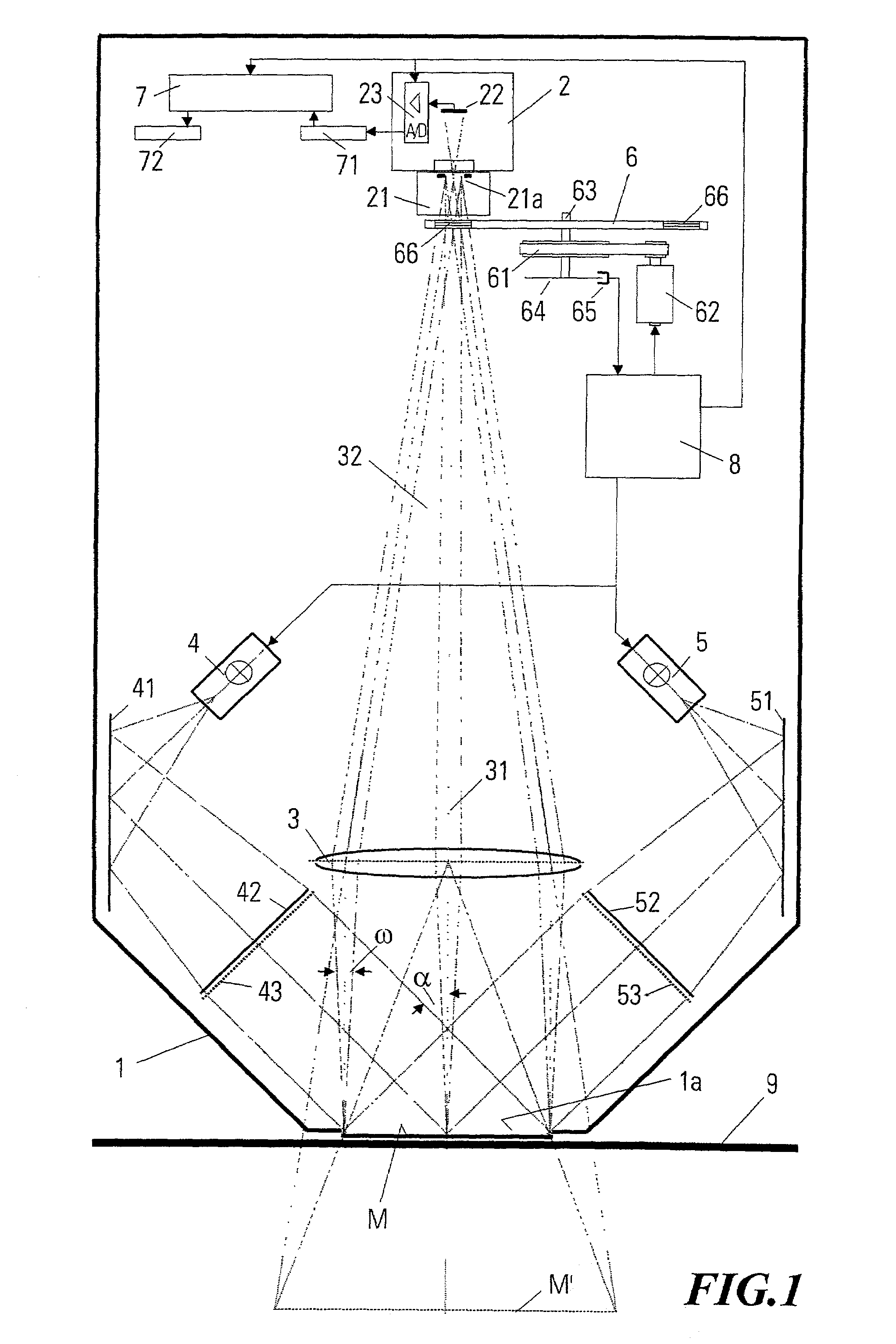
[0026]The first preferred embodiment of the measurement device in accordance with the invention as schematically illustrated in FIG. 1 includes a light-proof housing 1 with a measurement window 1a, a video camera 2, a tele-lens 3 preferably constructed as a Fresnel lens, two flash light sources 4 and 5, two re-directing mirrors 41 and 51, two illumination lenses 42 and 52 preferably constructed as Fresnel lenses, two blend filters 43 and 53 positioned at the illumination lenses, a filter wheel 6, a belt-drive 61, 62 an angle encoder 64 connected with the axis 63 of the filter wheel 6 and with an associated sensor 65, a data processor 7 and a central process control 8. The data processor 7 and the process control 8 are preferably realized by a digital computer and can of course be positioned outside the housing 1.

[0027]The video camera 2 is generally of conventional construction and includes, as parts relevant for the present invention, a standard imaging lens 21, an image sensor 22 ...


PUM


Abstract

The device for the pixel-by-pixel photoelectric measurement of a planar measured object includes projection means for the imaging of the measured object onto a two-dimensional CCD image sensor, filter means provided in the imaging light path for the wavelength selective filtering of the measuring light impinging on the image sensor, signal processing means for the processing of the electrical signals produced by the image sensor and for the conversion thereof into corresponding digital raw measured data, as well as data processing means for the processing of the raw measured data into image data representing the colors of the individual image elements of the measured object. Furthermore, illumination means are provided which include a Fresnel lens, which illuminate the measured object with at least one essentially parallel light bundle under an angle of incidence of essentially 45°+/−5°. The projection means which include at least one tele-lens constructed as a Fresnel lens, are constructed as tele-centrical imaging optics, which image each point of the measured object under essentially the same angle of observation of essentially 0° and with essentially the same aperture angle of essentially maximally 5° onto the light converter element array. The data processing means carry out extensive correction measures.

Description

[0001]This application claims priority under 35 U.S.C. §§ 119 and / or 365 to 00126493.6 filed in Europe on Dec. 8, 2000, and to 01105312.1 filed in Europe on Mar. 7, 2001; the entire contents of which are hereby incorporated by reference.FIELD OF THE INVENTION[0002]The invention relates to a device for the pixel-by-pixel photoelectric measurement of a planar or flat measured object or object to be measured.BACKGROUND ART[0003]So called scanners are used especially in the graphics industry for the pixel-by-pixel photoelectric scanning of planar measured objects. They include a measuring head which is moveable relative to the measured object in one or two dimensions, which captures the spectral remission of respectively one pixel of the measured object or object to be measured by way of a 0 / 45° measurement geometry and converts it into corresponding electric signals. Scanners equipped with fibre optics are also already known, which can measure a complete image line at once. However, sc...

Claims


Application Information

Patent Timeline
IPC IPC(8): G01N21/25G01J3/02G01J3/28G01J3/36G01J3/51G01J3/52G01N21/27G01N21/31G06T1/00H04N5/225H04N9/04
CPCG01J3/02G01J3/0208G01J3/28G01J3/2803G01J3/2823G01J3/36G01J3/524G01N21/251G01N21/27G01J3/51G01N2021/3174G01J3/52G01N21/274
Inventor OTT, HANS
Owner X RITE SWITZERLAND
Why Eureka
Try Eureka