
Integrated reaction wheel assembly and fiber optic gyro

a reaction wheel and fiber optic technology, applied in the field of attitude reference systems, can solve the problems of increasing mass, increasing the cost of both devices, and reducing the already limited space available on satellites, for exampl

Inactive Publication Date: 2006-06-06
HONEYWELL INT INC
View PDF2 Cites 8 Cited by
  • Summary
  • Abstract
  • Description
  • Claims
  • Application Information

AI Technical Summary

Benefits of technology

The patent describes a device that includes a reaction wheel assembly and a fiber optic gyro. The reaction wheel assembly has a housing and a coil made of fiber optic gyro integrated with the housing. The device also has electronics integrated with the reaction wheel assembly housing. The fiber optic gyro coil may be wound around the reaction wheel assembly housing or located within it. The technical effect of this invention is to provide a compact and efficient device for detecting and measuring rotation.

Problems solved by technology

Having both of these devices is expensive, results in increased mass, and reduces the already limited space available on, for example, satellites.
These problems may be exacerbated when improved FOG performance is desired because increased length-diameter product results in increased mass or volume.

Method used


Image

  • Integrated reaction wheel assembly and fiber optic gyro
  • Integrated reaction wheel assembly and fiber optic gyro
  • Integrated reaction wheel assembly and fiber optic gyro

Examples


Embodiment Construction

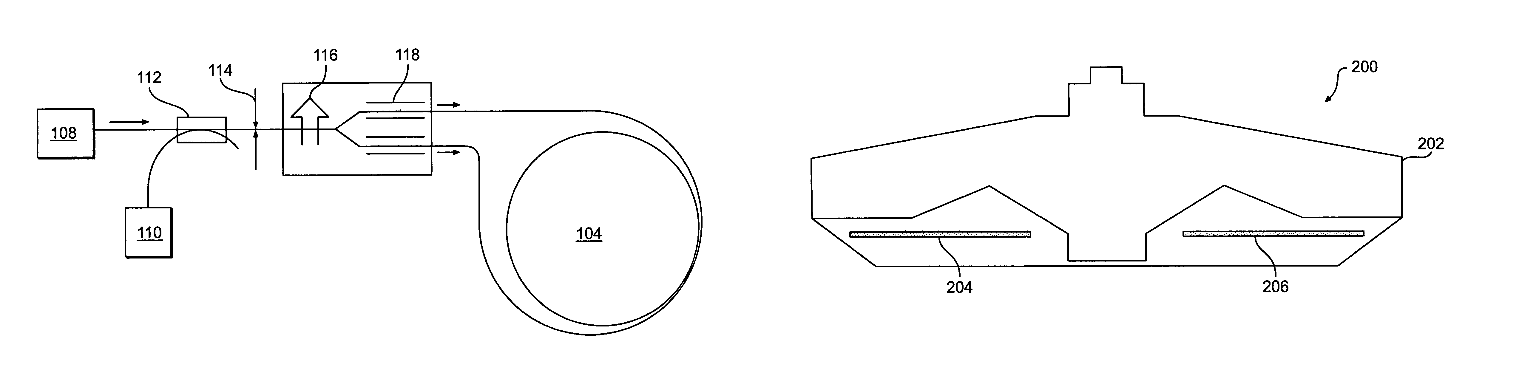
[0017]Three performance issues are of primary importance in optical gyroscopes. The first of these is bias stability, or the stability of the output when the sensor is exposed to a constant input rate. Bias stability is measured in degrees per hour. Two factors for achieving good bias stability in a FOG are maintaining the reciprocity of the optical path and controlling polarization errors. Maintaining reciprocity is a major goal of the entire optical design. Suppressing polarization errors calls for some additional steps.

[0018]There is an opportunity for cross coupling of the two polarization modes at every fiber splice. The number of beams is effectively doubled at each splice, until there are thousands of independent beams running through the sensor. Whenever one of the cross-coupled beams is coherent with the main signal beam, it adds some phase error to the gyroscope output. FOG designers have a number of tricks for suppressing these errors. Choosing a light source with a very ...


PUM


Abstract

The present invention relates to a reaction wheel assembly and fiber optic gyro device. The device includes a reaction wheel assembly having a reaction wheel assembly housing, a fiber optic gyro coil integrated with the reaction wheel assembly housing, and a fiber optic gyro electronics integrated with the reaction wheel assembly housing. The fiber optic gyro coil may be wound around the reaction wheel assembly housing. The gyro coil may also be located within the reaction wheel assembly housing.

Description

BACKGROUND[0001]1. Field of the Invention[0002]The present invention relates generally to an attitude reference system. More specifically, the present invention relates to an integrated reaction wheel assembly (RWA) and fiber optic gyro (FOG) that may be used in the aerospace industry.[0003]2. Background of the Invention[0004]As is well known, a FOG operates on a principal known as the Sagnac effect, which describes what happens when two beams of light travel in opposite directions around the same closed path. If the path is not rotating, the two beams complete their circuit and arrive back at the starting point at the same instant. When the structure is rotating about an appropriate axis, however, the two beams traverse different path lengths, i.e. the beam traveling in the direction of rotation travels a longer path and vice versa. This difference is small, but it can be detected and measured to indicate rotation rate.[0005]When light moves through a material medium, it remains de...

Claims


Application Information

Patent Timeline
Patent Type & Authority Patents(United States)
IPC IPC(8): G01C19/72B64G1/28G01C19/02
CPCB64G1/283G01C19/722B64G1/288Y10T74/1218B64G1/369
Inventor JACOBS, JACK H.MOULTON, ED C.
Owner HONEYWELL INT INC
Learn More