Display apparatus

a technology of display apparatus and display screen, which is applied in the field of display screen, can solve problems such as the possibility of an increase in power consumption, and achieve the effect of reducing the drive voltage and improving the luminance of the resul

Inactive Publication Date: 2006-06-06
CANON KK
View PDF8 Cites 29 Cited by
  • Summary
  • Abstract
  • Description
  • Claims
  • Application Information

AI Technical Summary

Benefits of technology

[0007]An object of the present invention is to provide a display apparatus capable of suppressing an increase in drive voltage.
[0008]Another object of the present invention is to provide a display apparatus capable of improving a luminance.
[0010]In the apparatus, the scattering layer is disposed between the first electrode (transparent electrode) and the reflection surface. Accordingly, it is possible to narrow a spacing between the first electrode and the second electrode, so that a drive voltage becomes small. In the present invention, another (second) scattering layer may be disposed between the first and second electrodes. In this case, the resultant scattering layer can be made thin, so that it is possible to suppress an increase in drive voltage. Further, the entire thickness of the scattering layers can be made thick by the presence of the first scattering layer. As a result, a resultant luminance is improved.

Problems solved by technology

As a result, there is a possibility of an increase in power consumption.

Method used


Image

  • Display apparatus
  • Display apparatus

Examples


example 1

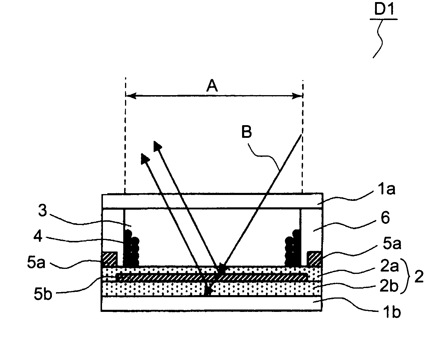
[0028]An electrophoretic display apparatus D1 having the structure shown in FIG. 1 was prepared in in the following manner.

[0029]A first substrate 1a and a second substrate 1b were disposed with a predetermined spacing. On the surface of the second substrate 1b, a scattering layer 2b, a second electrode 5b, and a scattering layer 2a were disposed in this order. At a boundary between adjacent pixels A, a first electrode 5a and a partition (wall) member 6 were disposed so as to partition the pixels A (in FIG. 1, only one pixel A is shown for convenience). At each pixel A, an insulating liquid 3 and charged particles 4 were disposed.

[0030]As a material for the scattering layers 2a and 2b, an urethane resin containing titanium oxide having a particle size of 0.5 μm was used and formed in a white scattering layer. The scattering layer 2a had a thickness of 3 μm and the scattering layer 2b had a thickness of 500 μm. The second electrode 5b was formed of transparent ITO (indium tin oxide) ...

example 2

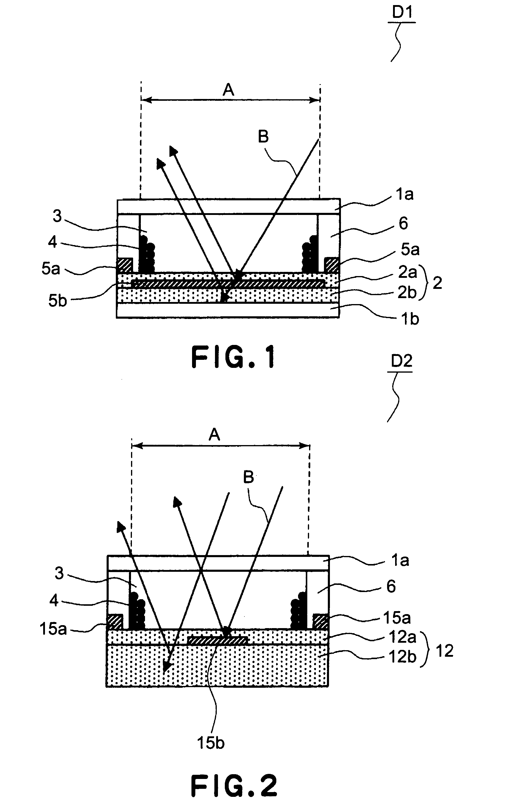
[0032]An electrophoretic display apparatus D2 having the structure shown in FIG. 2 was prepared in the same manner as in Example 1 except for the following points.

[0033]The second substrate 1b was not used, and scattering layers 12a and 12b were used as a support instead of the second substrate 1b. A second electrode 15b was formed of aluminum and disposed in an area having an area portion of 20% per the entire pixel A area. A 1 mm-thick scattering layer 12b was formed of PET (polyethylene terephthalate) containing titanium oxide, and a 2 mm-thick scattering layer 12a was formed of an acrylic resin containing titanium oxide.

[0034]When the electrophoretic display apparatus was driven, a drive voltage could be lowered to ±8 V and it was possible to realize a maximum reflectance of 46%.


PUM

PropertyMeasurementUnit
particle sizeaaaaaaaaaa
thicknessaaaaaaaaaa
thicknessaaaaaaaaaa

Abstract

An apparatus includes a substrate, charged particles, a transparent electrode disposed in parallel with a surface of the substrate, an electrode disposed at a periphery of the transparent electrode, means for applying a voltage between the transparent electrode and the electrode disposed at the periphery thereof to move the charged particles laterally, a reflection surface for reflecting light incident onto in the substrate, and a light scattering or absorption layer disposed between the transparent electrode and the reflection surface. The apparatus is effective in providing a desired scattering ability without increasing a drive voltage.

Description

FIELD OF THE INVENTION AND RELATED ART[0001]The present invention relates to a display apparatus, particularly an electrophoretic display apparatus which effects display based on movement of charged particles.[0002]Electrophoretic display apparatuses having various structures have been conventionally proposed with respect to such an electrophoretic display apparatus for performing display based on movement of charged particles.[0003]For example, Japanese Laid-Open Patent Application (Tokkaihei) 11-202804 and (Tokuhyo) 2002-504696 have disclosed an electrophoretic display apparatus in which an insulating liquid, charged particles and electrodes are disposed between a pair of substrates disposed with a spacing therebetween and the charged particles are moved by applying a voltage to the electrodes.[0004]The electrophoretic display apparatuses include those of a reflection type and a transmission type. In the case of the reflection type electrophoretic display apparatus, a scattering l...

Claims


Application Information

Patent Timeline
Patent Type & Authority Patents(United States)
IPC IPC(8): G02B26/00G02F1/167G02F1/1677
CPCG02F1/167G02F1/1677
Inventor UKIGAYA, NOBUTAKA
Owner CANON KK
Why Eureka
Try Eureka