
Water cut rate of change analytic method

a technology of water cut rate and change, applied in the direction of survey, instruments, borehole/well accessories, etc., can solve the problems of loss of oil by leaving oil in the ground, water production too high to be lifted to the surface, poor sweep efficiency, etc., and achieve the effect of rapid identification

Inactive Publication Date: 2006-06-13
SAUDI ARABIAN OIL CO
View PDF19 Cites 12 Cited by
  • Summary
  • Abstract
  • Description
  • Claims
  • Application Information

AI Technical Summary

Benefits of technology

The present invention provides a new method for measuring the impact of water on non-water wells in oil reservoirs. This method uses a history of water cut measurements over an extended period of time to determine the rate at which water is cutting into the well. By measuring the water cut rate of change, the method can identify areas where the water cut is increasing at a faster rate than other wells in the area. This method can be used for oil reservoir management, reservoir characterization, reservoir simulation, and production strategies. It also allows for the rapid identification of geological and oil field heterogeneities and anomalies.

Problems solved by technology

Oil wells are usually dry when first drilled, which means that they produce only oil.
The more water wet the well becomes, the lower the net oil rate is, to the point where the water production becomes too high to be lifted to the surface.
Poor sweep efficiency is a result of water bypassing most of the oil by channeling through and reaching the oil producing wells.
This in return will result in loss by leaving oil in the ground.

Method used


Image

  • Water cut rate of change analytic method
  • Water cut rate of change analytic method
  • Water cut rate of change analytic method

Examples


Embodiment Construction

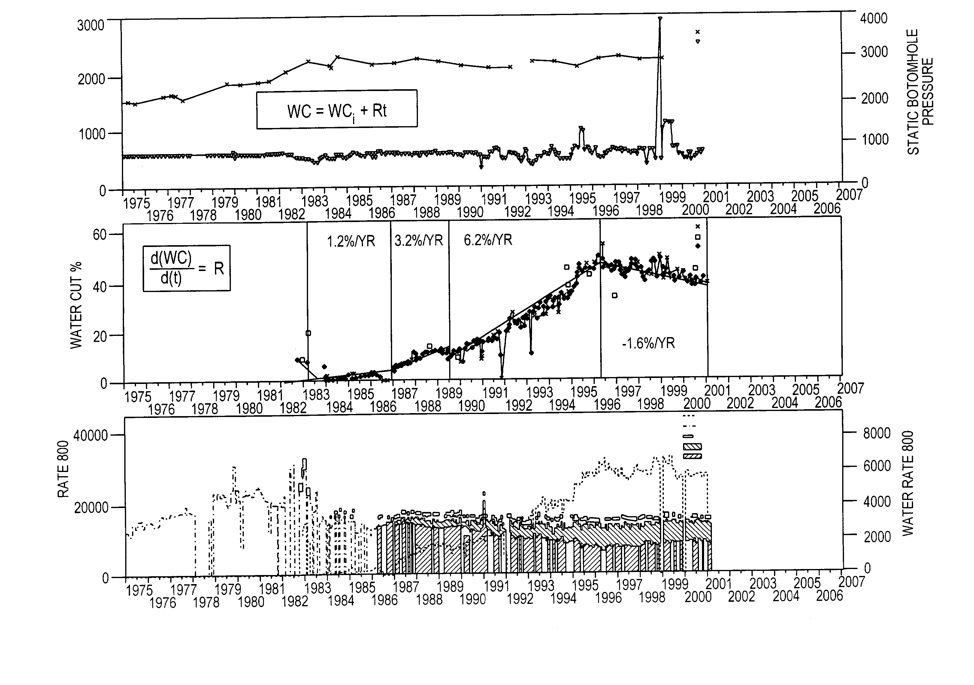
[0038]As described above, the prior art has been concerned with water cut percentage at a certain point of time as defined above in units of percent. However, the new WCRC technique has to do with the rate of change of water cut over time and its unit is in percent per unit time, e.g. percent per year or percent per month.

[0039]In addition, while the prior art dealt with the current measured water cut percentage, WCRC encompasses historical water cut behavior including the present and then is used to predict future performance. WCRC is obtained through manipulating the measured water cut by calculating the derivative or rate of change of water cut percentage with respect to time.

Definition of the Linear WC Rate of Change (WCRC)

[0040]The definition of WCRC is as follows. Assume a linear WC that increases with respect to time. Therefore, WC at any point of time is equal to the initial WC=WC1 plus the WCRC or “R” multiplied by time.

WC=WC1+Rt  (2)

[0041]By differentiating this equation, ...


PUM

PropertyMeasurementUnit
timeaaaaaaaaaa
pressureaaaaaaaaaa
pressureaaaaaaaaaa

Abstract

A method of measuring a water effect on an underground non-water well includes the steps of assembling a history of water cut (WC) measurements for the well over an extended period of time, determining a water cut rate of change (R) for the well based upon the history of water cut measurements, wherein the water cut rate of change is defined as follows:ⅆ(WC)ⅆ(t)=R,and identifying whether an anomaly exists based on the determined R.

Description

FIELD OF THE INVENTION[0001]This invention relates to the measurement of water in oil wells.BACKGROUND OF THE INVENTION[0002]Oil wells are usually dry when first drilled, which means that they produce only oil. However, after an oil well has been in production for a period of time, which may be ten to fifteen years or more, the well may begin to co-produce water with the crude oil flow. The water is typically an incursion from a local aquifer that begins to move through the reservoir rock as the oil pressure is lowered. The more water wet the well becomes, the lower the net oil rate is, to the point where the water production becomes too high to be lifted to the surface. At this point, the percentage of oil in proportion to the water cut may be so low, or be reduced to zero, so as to take the well out of production. Therefore, water production must be controlled so as not to lose oil production.[0003]In addition to naturally occurring water incursions, it is often the practice to pu...

Claims


Application Information

Patent Timeline
Patent Type & Authority Patents(United States)
IPC IPC(8): G01N33/26G06F17/17G01N33/28
CPCG01N33/2823
Inventor AL-GHAMDI, ABDULLA H.
Owner SAUDI ARABIAN OIL CO
Learn More