Multi-stage sliding air throttle valve assembly and cylinder assembly engine including same

a technology of sliding air throttle valve and cylinder assembly, which is applied in the direction of combustion air/fuel air treatment, machines/engines, fuel air intakes, etc., can solve the problems of limiting the size and undesirable valves

Inactive Publication Date: 2006-06-13
CLARK ARVEL L
View PDF2 Cites 16 Cited by
  • Summary
  • Abstract
  • Description
  • Claims
  • Application Information

AI Technical Summary

Problems solved by technology

However, such valves have been found to be rather undesirable when incorporated into outboard engines used in motorboat racing, where fine tuning is required for peak torque at specific rpm's.
The slide-type valve design disclosed in the '612 patent is disadvantageous because it necessarily limits the size of the air ports through the valve assembly.

Method used


Image

  • Multi-stage sliding air throttle valve assembly and cylinder assembly engine including same
  • Multi-stage sliding air throttle valve assembly and cylinder assembly engine including same
  • Multi-stage sliding air throttle valve assembly and cylinder assembly engine including same

Examples


Embodiment Construction

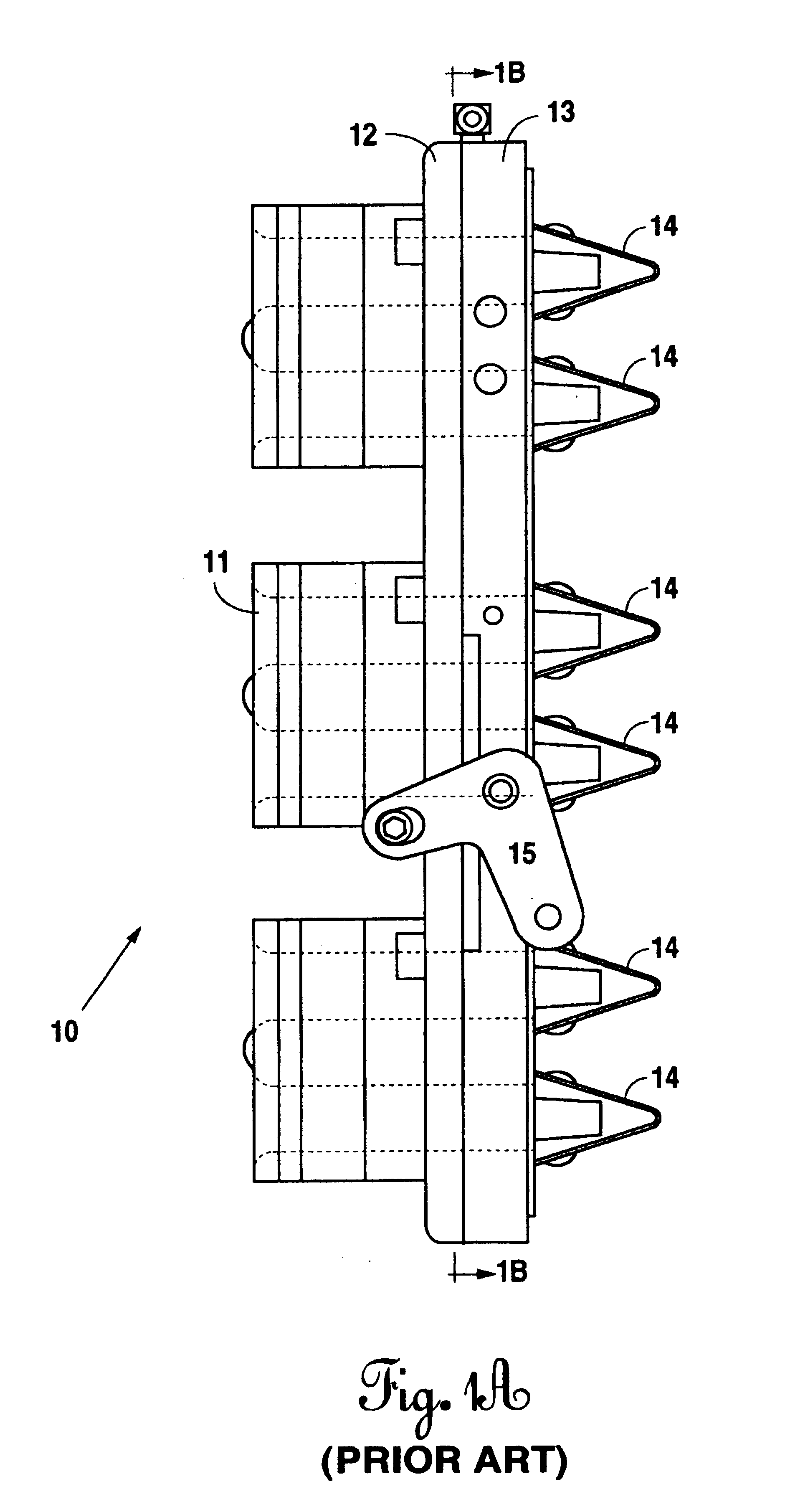
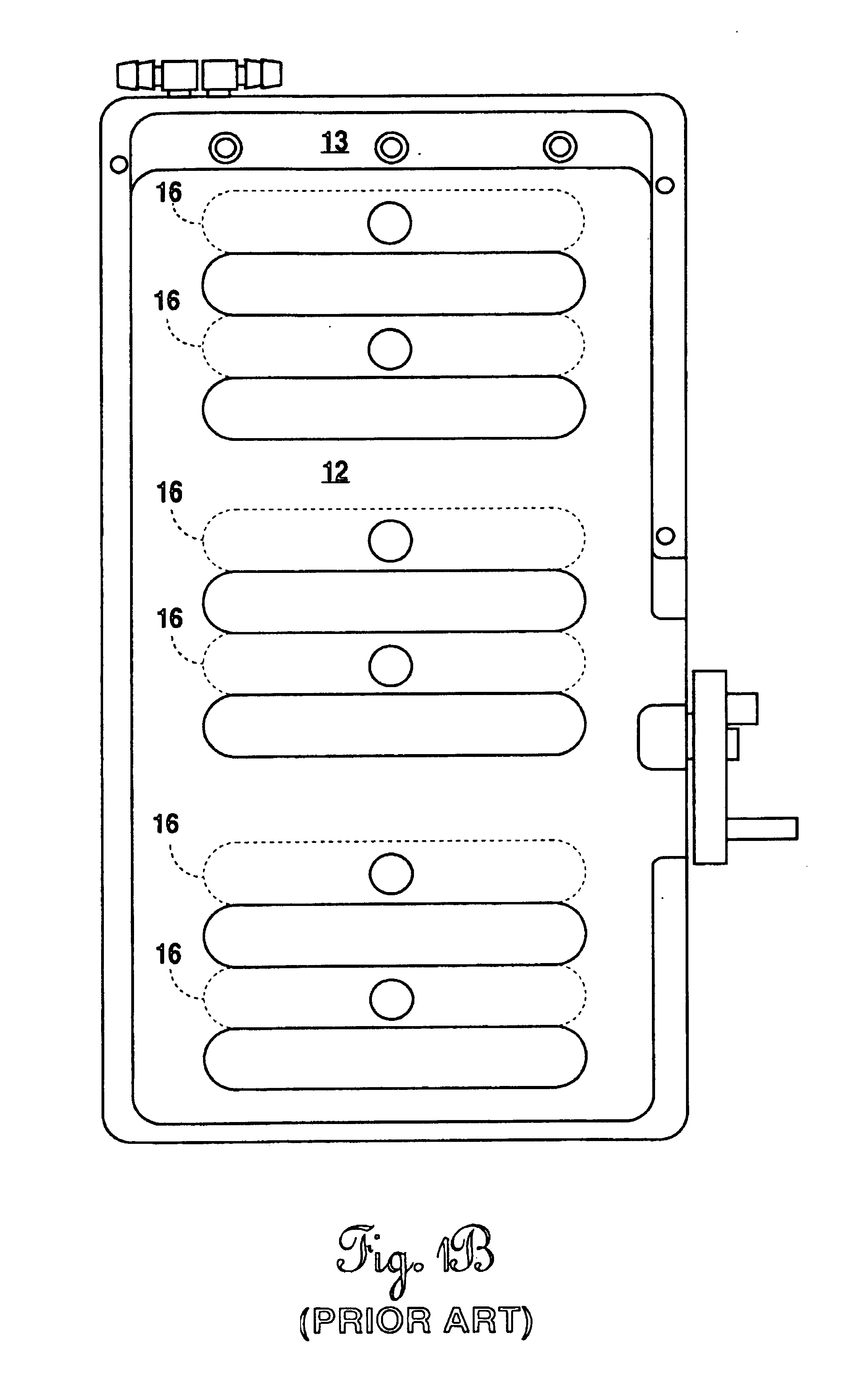
[0029]With first reference to FIG. 1A, there is shown a prior art throttle valve device 10. The illustration and the device 10 are as illustrated and described in U.S. Pat. No. 5,636,612, entitled “Adjustable Air Velocity Stacks For Two-Stroke Fuel Injected Engines”, issued Jun. 10, 1997. FIG. 1A is based upon the illustration of FIG. 11 of the '612 prior art patent. The prior art device 10 shows aan air velocity stack 11 on the intake side of the device 10 and secured to a single valve plate component 12 slidably affixed onto a throttle valve housing 13. A series of Reed valve assemblies 14e are also provided and are likewise affixed to the valve housing 13. The entire assembly is thus arranged and the housing is secured to the motor block (not shown) such that one Reed valve 14 is introduced within each respective ignition cylinder chamber (not shown) within the motor block. An armature 15 is provided to shift the single valve plate between opening and closing positions across the...


PUM


Abstract

A multi-stage air throttle valve assembly is provided for use in a multiple cylinder engine. The valve assembly provides a series of shiftable valve plates to provide full, maximum opening of air ports having passageways therethrough for introduction of air into the combustion cylinders of the engine. By use of two or more such sliding plates, the port size through the assembly may be maximized for enhanced volumetric entry of air into the combustion chambers. A combined reed valve assembly, fuel injectors and / or an air velocity assembly with engine are also disclosed.

Description

BACKGROUND OF THE INVENTION[0001](1) Field of the Invention[0002]The invention relates to multi cylinder internal combustion engines, such as, for use on boats, motorcycles, and the like.[0003](2) Brief Description of the Prior Art[0004]It is well known that the speed at which a vehicle may be moved is highly dependent upon the power generated by the engine for that vehicle. Internal combustion, two cylinder engines fueled by a hydrocarbon fuel and mixture of air are common in vehicles, especially outboard motors for speed boats, and the like. It is always an objective of such engine design to incorporate air flow or intake systems which will permit maximum entry of air into the combustion cylinders. Quick adjustment of the air flow characteristics into the cylinders is very desirable to increase or decrease the speed of the boat In the past, butterfly valves have been used as a throttling system for air intake. However, such valves have been found to be rather undesirable when inco...

Claims


Application Information

Patent Timeline
Patent Type & Authority Patents(United States)
IPC IPC(8): F02D9/00F02B27/02F02D9/08F02D9/14F02M1/16F02M9/06F02M35/10
CPCF02B27/02F02D9/14F02M9/06F02M1/16Y02T10/146F02B27/0236F02B27/0294Y02T10/12
Inventor CLARK, ARVEL L.
Owner CLARK ARVEL L
Why Eureka
Try Eureka