
Conveyer oven

a conveyer oven and oven body technology, applied in the field of conveyer ovens, can solve the problems of inability to obtain high heat efficiency, difficult to effectively utilize hot air, and worse working environment, so as to improve cooking efficiency, effectively use the remaining hot air in the heating chamber, and improve the effect of heating efficiency

Inactive Publication Date: 2006-06-13
PALOMA
View PDF22 Cites 28 Cited by
  • Summary
  • Abstract
  • Description
  • Claims
  • Application Information

AI Technical Summary

Benefits of technology

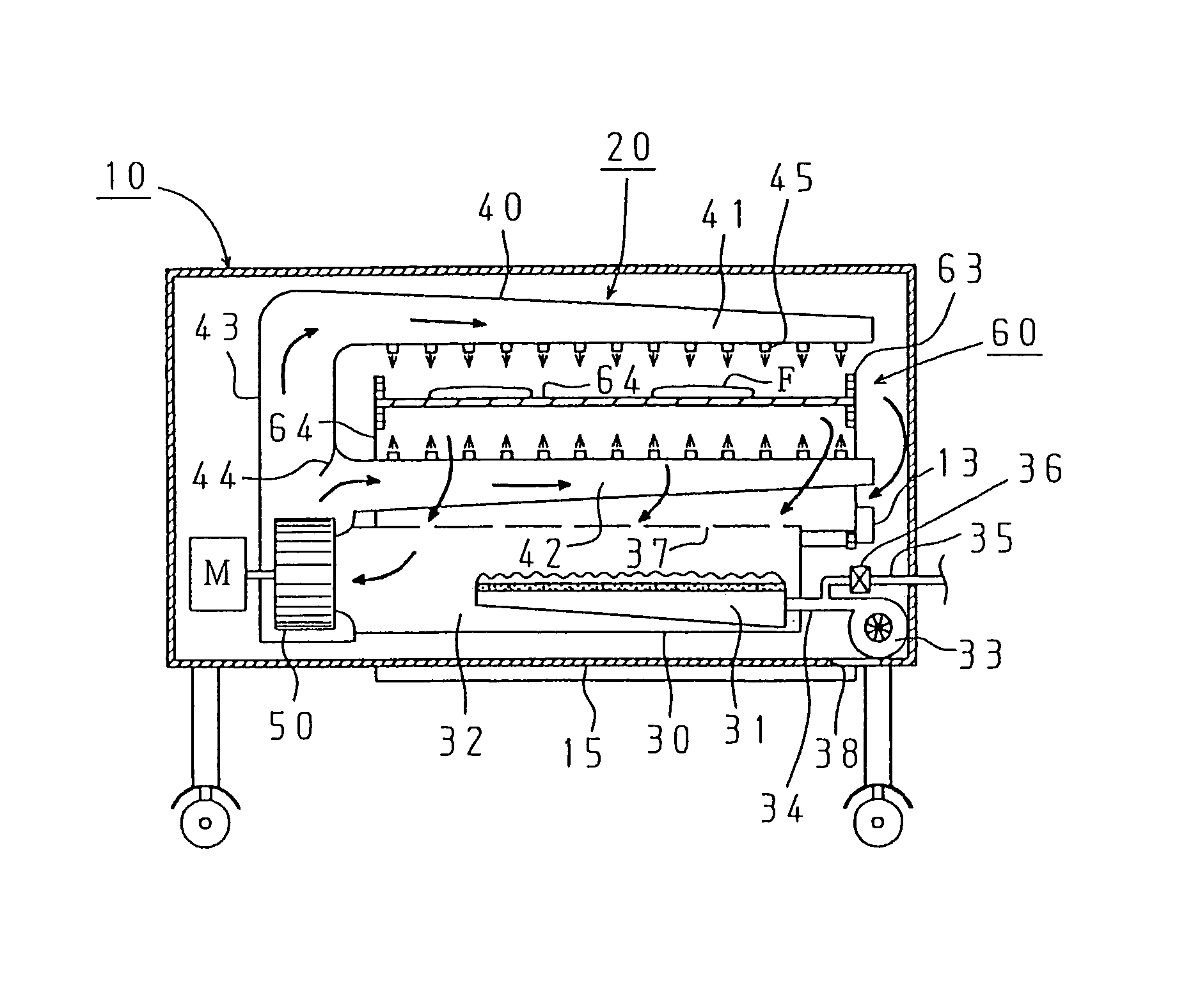
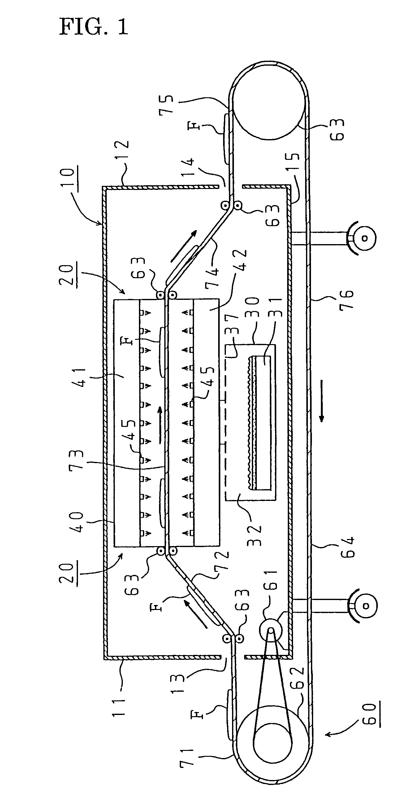
The present invention provides a conveyor oven with a heating chamber for heating foods, a conveyor for carrying the foods into and out of the heating chamber, and a heating means for heating the foods while they are conveyed. The heating means can be a heating chamber that blows hot air or applies radiant heat to the foods. The conveyor can convey the foods upward, allowing the heating means to efficiently use the remaining hot air and heat the foods evenly. The technical effects of the invention are improved cooking efficiency and even heating of the foods.

Problems solved by technology

Therefore, it is difficult to utilize the hot air effectively, and the conveyer oven is unable to obtain high heat efficiency.
As a result, working environment becomes worse.

Method used


Image

  • Conveyer oven
  • Conveyer oven
  • Conveyer oven

Examples


second embodiment

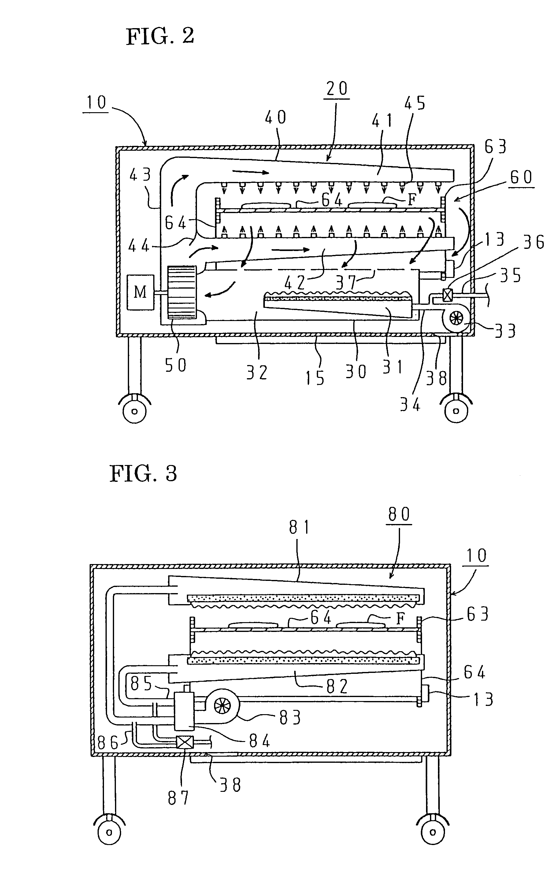
[0050]A heating means 80 in the second embodiment heats foods F by radiant heat. It includes an upper burner 81 and a lower burner 82 provided above and below the cooking route 73 of the conveyer 60 so that they are facing to each other, a combustion fan 83 for commonly supplying combustion air to the burners 81, 82, a distributor 84 for distributing the combustion air to the burners 81, 82 from the combustion fan 83, an air supply tube 85 for guiding the distributed combustion air to the burners 81, 82, a gas supply tube 86 for mixing fuel gas to the air supply tube 85, and a gas control valve 87 for opening / closing of the gas supply tube 86, such as an electromagnetic valve.

[0051]The upper burner 81 and the lower burner 82 are all primary air combustion burners each of which is made of ceramic plates facing each other and having a plurality of flame ports. Foods F are heated by both radiant heat from the ceramic plates and hot combustion gas.

[0052]Similarly to the first embodiment...

first embodiment

[0053]Similarly to the first embodiment, in this case remaining hot air at the upper portion of the heating chamber 10 is also used for heating. As a result, several advantageous effects are obtained, such as improvement of cooking performance caused by even heating, improvement of heat efficiency, maintenance of a room temperature in a moderate range, reduction of fuel cost.

[0054]The embodiments of the present invention are thus explained, but this invention is not limited to the above embodiments and can be modified diversely without departing a scope of the present invention.

[0055]For example, the heating means may be configured so that it supplies only hot air into the heating chamber 10 without a direct blow of hot air to the surfaces of the foods F. In this case, the remaining hot air in the heating chamber 10 surrounds and heats the foods F.

[0056]It should be noted that a height where the foods are conveyed upward can be arbitrary set, but it is desirable to set the height wh...


PUM


Abstract

An object of the present invention is to provide a conveyer oven having a high heat efficiency and excellent cooking performance. Foods F are carried into a heating chamber 10 by a conveyer 60 and conveyed to the upper portion of the heating chamber. While the foods F are conveyed at the upper portion of the heating chamber, an eject nozzle 45 blows hot air to the foods F and simultaneously foods F are surrounded with remaining hot air. When cooking is finished, the foods F are conveyed downward to be carried out from the heating chamber 10. Therefore, heat from a heating means 20 is used effectively for cooking, that means heat efficiency is improved, which reduces fuel cost. Moreover, since the foods F are surrounded with remaining hot air, the foods F are evenly heated all over, whereby cooking performance is improved.

Description

[0001]This application claims the benefit of Japanese Patent Application Number 2003-66283 filed on Mar. 12, 2003, the entirety of which is incorporated by reference.BACKGROUND OF THE INVENTION[0002]1. Field of the Invention[0003]The present invention relates to a conveyer oven for commercial use in which foods, such as a pizza, are placed on a conveyer and heated.[0004]2. Description of the Related Art[0005]Conventionally, in fast food stores, a conveyer oven is used for heating foods, such as a pizza.[0006]The description of such a conveyer oven is disclosed in Japanese Patent Publication of Examined Application 3-3126. It includes a heating chamber for heating foods, a conveyer that penetrates the heating chamber horizontally for carrying the foods into the heating chamber, and a heating means provided in the heating chamber for heating the foods which are placed on the conveyer from the top and the bottom of the foods.[0007]The foods are placed on the conveyer and carried into t...

Claims


Application Information

Patent Timeline
Patent Type & Authority Patents(United States)
IPC IPC(8): F24C15/32B65G47/57A21B1/24A21B1/48A23L5/10A47J37/04F24C1/00
CPCA21B1/245A47J37/044A21B1/48Y02P60/80
Inventor KOBAYASHI, TOSHIHIRO
Owner PALOMA
Learn More