Motor-cooling structure of front-and-rear-wheel-drive vehicle

a front-and-rear-wheel drive, motor cooling technology, applied in the direction of electric propulsion mounting, vehicle sub-unit features, transportation and packaging, etc., can solve the problems of increasing the weight of the overall system the increase of the overall system weight, and the like, so as to achieve the effect of significantly enhancing the motor cooling effect, significantly reducing the oil-agitation resistance provided by the driven gear, and increasing the overall system weigh

Active Publication Date: 2006-06-13
HONDA MOTOR CO LTD
View PDF15 Cites 45 Cited by
  • Summary
  • Abstract
  • Description
  • Claims
  • Application Information

AI Technical Summary

Benefits of technology

[0008]Accordingly, it is an aspect of the present invention to provide, in a hybrid vehicle wherein a driving force of a motor is transmitted to driven wheels through a differential, a motor that is effectively cooled using the lubricating oil for the differential.
[0010]With the above arrangement, the oil splashed from the oil sump by the driven gear of the differential is stored in the first and second storage chambers and then supplied therefrom into the motor shaft to cool the motor, rather than sprinkling the oil splashed from the oil sump by the driven gear of the differential directly onto the motor to cool the motor. Therefore, a motor-cooling effect is significantly enhanced without requiring a special radiator and a special cooling-water pump. Moreover, an oil surface in the oil sump is lowered in correspondence to an amount of the oil stored in the first and second oil storage chambers, so that oil-agitation resistance provided by the driven gear is significantly decreased.
[0017]With the above arrangement, because the second oil storage chamber and the oil sump are partitioned from each other by the partition wall, the oil in the second oil storage chamber is prevented from flowing therefrom into the oil sump by the inclination of a road surface or by a longitudinal acceleration of the vehicle. Accordingly, supply of oil to the motor by the oil supply means is reliably carried out.
[0019]With the above arrangement, because the clutch is disposed between the driven gear and the differential, the oil supply means and the driven gear are stopped by cutting-off the clutch when the motor is stopped, thereby decreasing the oil-agitation resistance.

Problems solved by technology

Additionally, the number of parts, overall system weight, friction resistance, cost, and the like is not increased.

Method used


Image

  • Motor-cooling structure of front-and-rear-wheel-drive vehicle
  • Motor-cooling structure of front-and-rear-wheel-drive vehicle
  • Motor-cooling structure of front-and-rear-wheel-drive vehicle

Examples


Embodiment Construction

[0032]The present invention will now be described by way of a preferred embodiment with reference to the accompanying drawings.

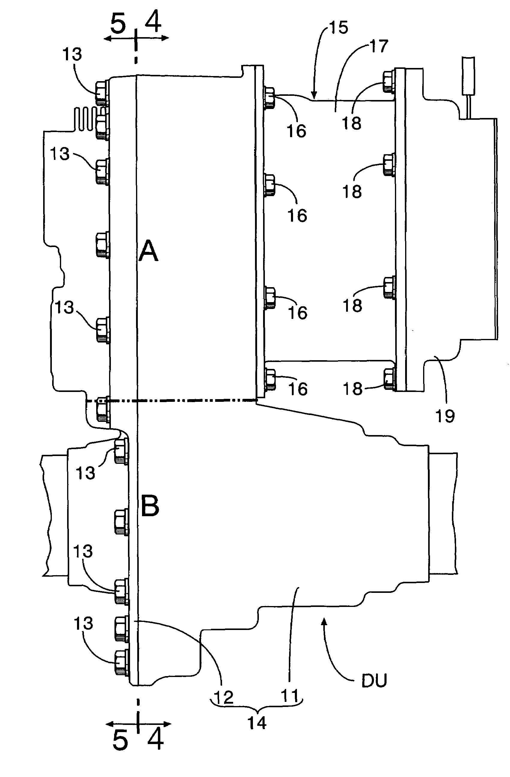
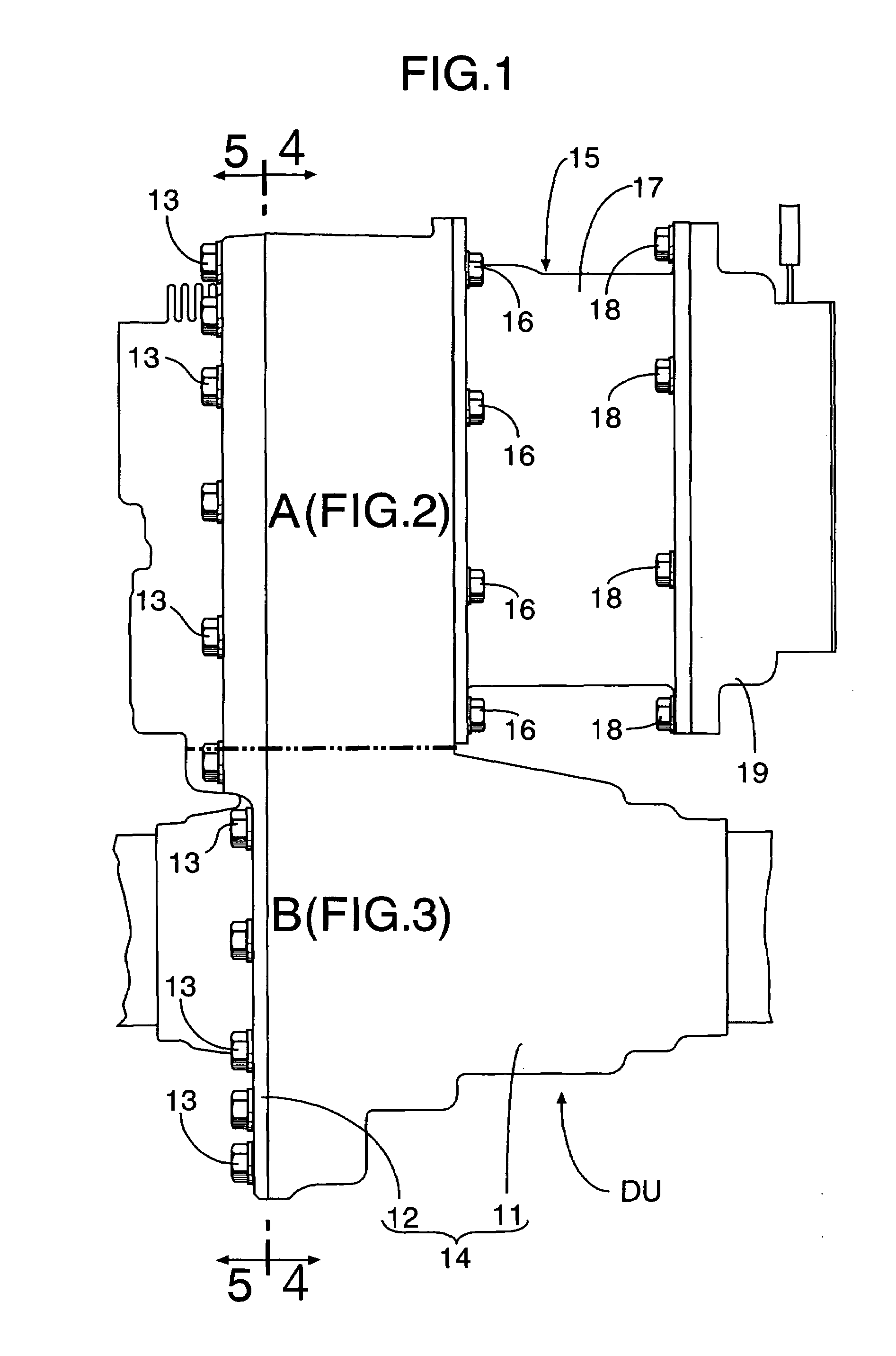
[0033]FIG. 1 shows the contour of a driving unit DU for rear wheels mounted on a front-and-rear-wheel-drive vehicle, wherein front wheels, i.e., first driven wheels, are driven by an engine, and rear wheels, i.e., second driven wheels, are driven by a motor.

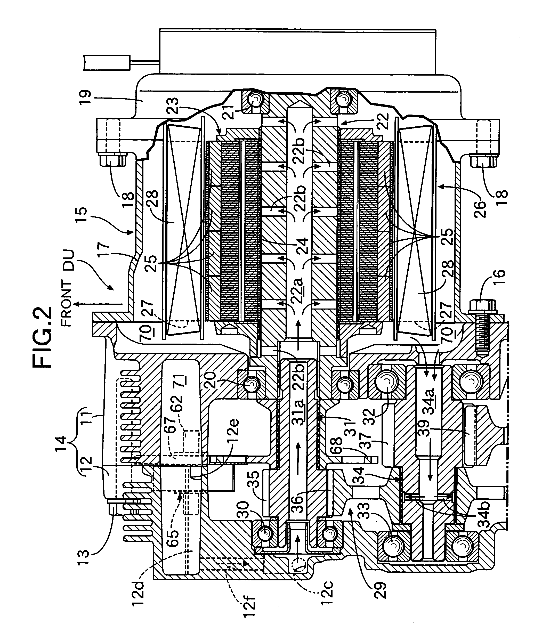
[0034]As also shown in FIGS. 2 and 3, the driving unit DU includes a casing 14 having a casing body 11 and a casing cover 12 fastened to each other using a plurality of bolts 13. A motor 15 is mounted to a right side of a front portion of the casing body 11 by a plurality of bolts 16. The motor 15 includes a cylindrical motor housing 17 fastened to the casing body 11 by the bolts 16. A motor cover 19 is fastened to the motor housing 17 by a plurality of bolts 18 to cover a right side of the motor housing 17. A motor shaft 22 is rotatably supported by the casing body 11 and motor cover 19 using ball bearin...


PUM


Abstract

A rear wheel driving unit of a hybrid vehicle includes an oil catch tank that stores oil splashed from an oil sump formed on a bottom of a casing body by a driven gear of a differential. A slinger chamber to which the oil is supplied from the oil catch tank has a slinger disposed therein that is driven by the motor through gears. To cool the motor, the oil is supplied from the oil catch tank to an oil passage in a main shaft leading to the inside of a motor shaft by gravitational force. The oil splashed from the slinger chamber by the slinger is supplied to the oil passage to effectively cool the motor using the lubricating oil from the differential.

Description

BACKGROUND OF THE INVENTION[0001]1. Field of the Invention[0002]The present invention relates to a motor-cooling structure of a front-and-rear-wheel-drive vehicle having an engine adapted to drive first driven wheels and a motor adapted to drive second driven wheels, wherein a driving force of the motor is transmitted to the second driven wheels through a reduction unit and a differential.[0003]2. Description of the Related Art[0004]A hybrid vehicle is disclosed in Japanese Patent Application Laid-open Nos. 5-310048 and 6-38303, wherein driven wheels are driven by an engine and / or a motor. A lubricating oil is drawn by a special electric pump and is used to cool the motor.[0005]A hybrid vehicle is disclosed in Japanese Patent Application Laid-open No. 2001-333507, wherein front wheels are driven by an engine, rear wheels are driven by a motor, and a generator driven by the engine is cooled by engine cooling water.[0006]However, in the hybrid vehicle disclosed in Japanese Patent Appl...

Claims


Application Information

Patent Timeline
Patent Type & Authority Patents(United States)
IPC IPC(8): B60K17/356B60K1/00B60K17/354B60L50/16F16H57/04H02K7/10H02K7/14H02K9/19
CPCB60K6/405B60K17/354F16H57/0412B60K6/26B60K1/00Y02T10/6265B60K2001/003F16H57/0426F16H57/043F16H57/045F16H57/0476F16H57/0483F16H57/0495H02K7/10H02K7/14H02K9/19B60Y2306/03B60K2001/006Y02T10/62
Inventor KIRA, NOBUHIRO
Owner HONDA MOTOR CO LTD
Why Eureka
Try Eureka