Air circulation system

a circulation system and air technology, applied in ventilation systems, lighting and heating apparatus, heating types, etc., can solve the problems of miscalculation of the moving air mass, contamination concerns, and incorrect calculation of the air mass moving through each of the damper units, so as to restrict the build-up of combustion by-products, and effectively restrict the effect of combustion by-products

Inactive Publication Date: 2006-06-13
MESTEK
View PDF10 Cites 40 Cited by
  • Summary
  • Abstract
  • Description
  • Claims
  • Application Information

AI Technical Summary

Benefits of technology

[0014]It is another object of the present invention to provide an air circulation system which effectively restricts the build-up of combustion by-products to within a predetermined safety range.
[0015]It is another object of the present invention to provide an air circulation system which effectively restricts the build-up of combustion by-products to within a predetermined safety range by limiting the allowable temperature rise through the system.
[0016]It is another object of the present invention to provide an air circulation system which utilizes sensor arrays and an automated controller to effectively restrict the build-up of combustion by-products to within a predetermined safety range.
[0017]It is another object of the present invention to provide an air circulation system which automatically and periodically self-calibrates itself to ensure maximum efficiency and safety.

Problems solved by technology

These systems, however, are somewhat problematic as the fuel utilized by a given burner apparatus also inherently passes the by-products of combustion into the air mass itself during the heating process, thus leading to contamination concerns.
Should there exist problems with the structural integrity of the mechanical linkages in the damper units, or if there are any other environmental or structural complications, the sensors will misreport the actual position of the louvers, and hence, determination of the air mass moving through each of the damper units will be erroneously calculated.
Moreover, the presence of dirty or blocked filters within a DPS system may also cause a miscalculation of the moving air mass, a miscalculation which DPS systems are unable to detect or compensate for.
It will therefore be readily apparent that determining the ventilation rate from the indirect sensing of an air mass moving through a damper unit, as in known DPS systems, is susceptible to a myriad of structural and environmental factors which detrimentally affect the accuracy of the system as a whole.
In addition, the inaccuracy of DPS systems only tend to increase in magnitude the longer the systems are in use.
Other known systems, such as CO2-based systems, exist to address the contamination concerns of direct-fired systems, however these systems also suffer from operational shortcomings due to the detrimental effect that altitude and humidity, amongst other environmental concerns, have on the accuracy of the system.
Moreover, CO2-based systems have inherently limited measurement ranges which typically require large amounts of outside air to be heated, thus raising operating and maintenance costs.

Method used


Image

  • Air circulation system
  • Air circulation system
  • Air circulation system

Examples


Embodiment Construction

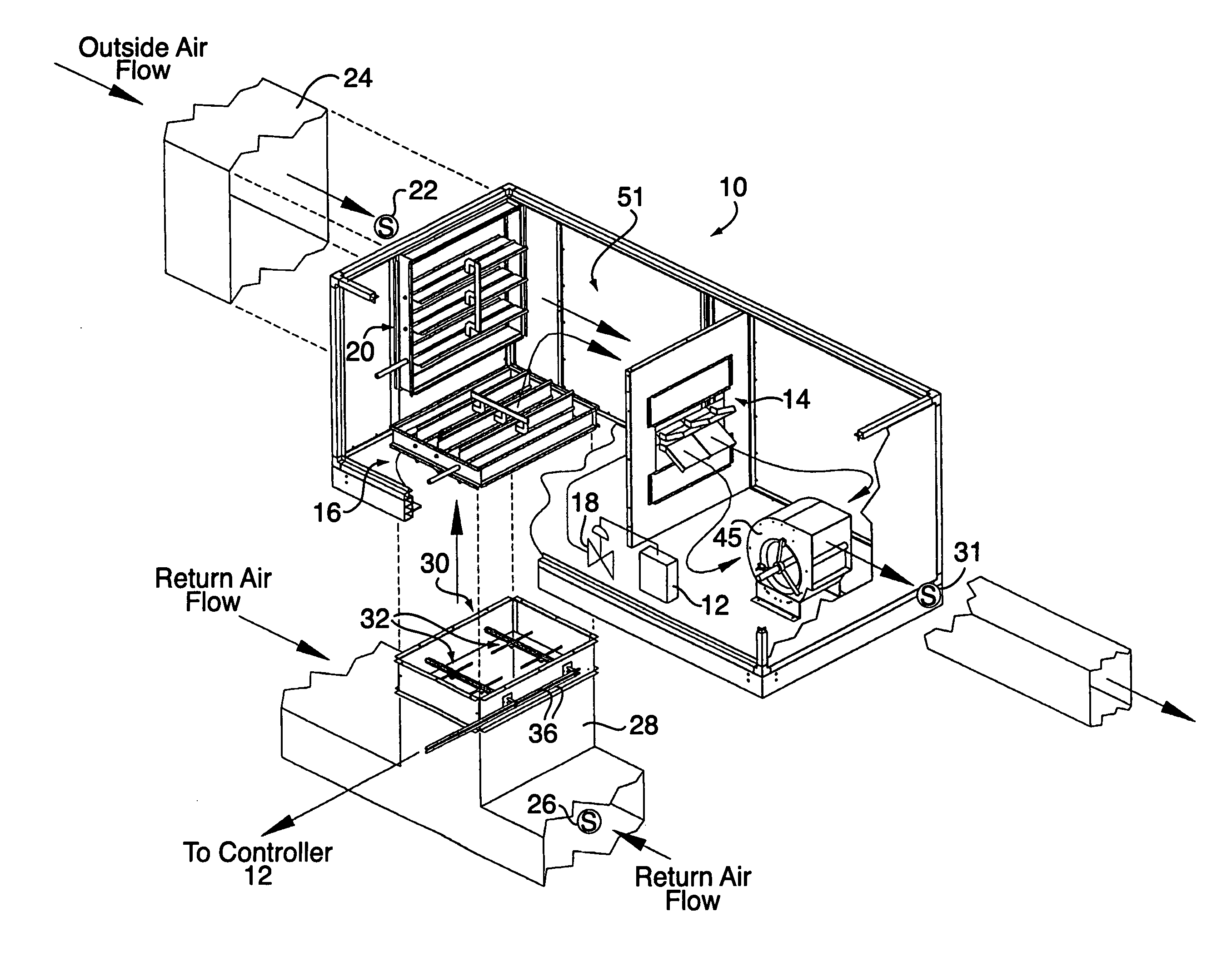
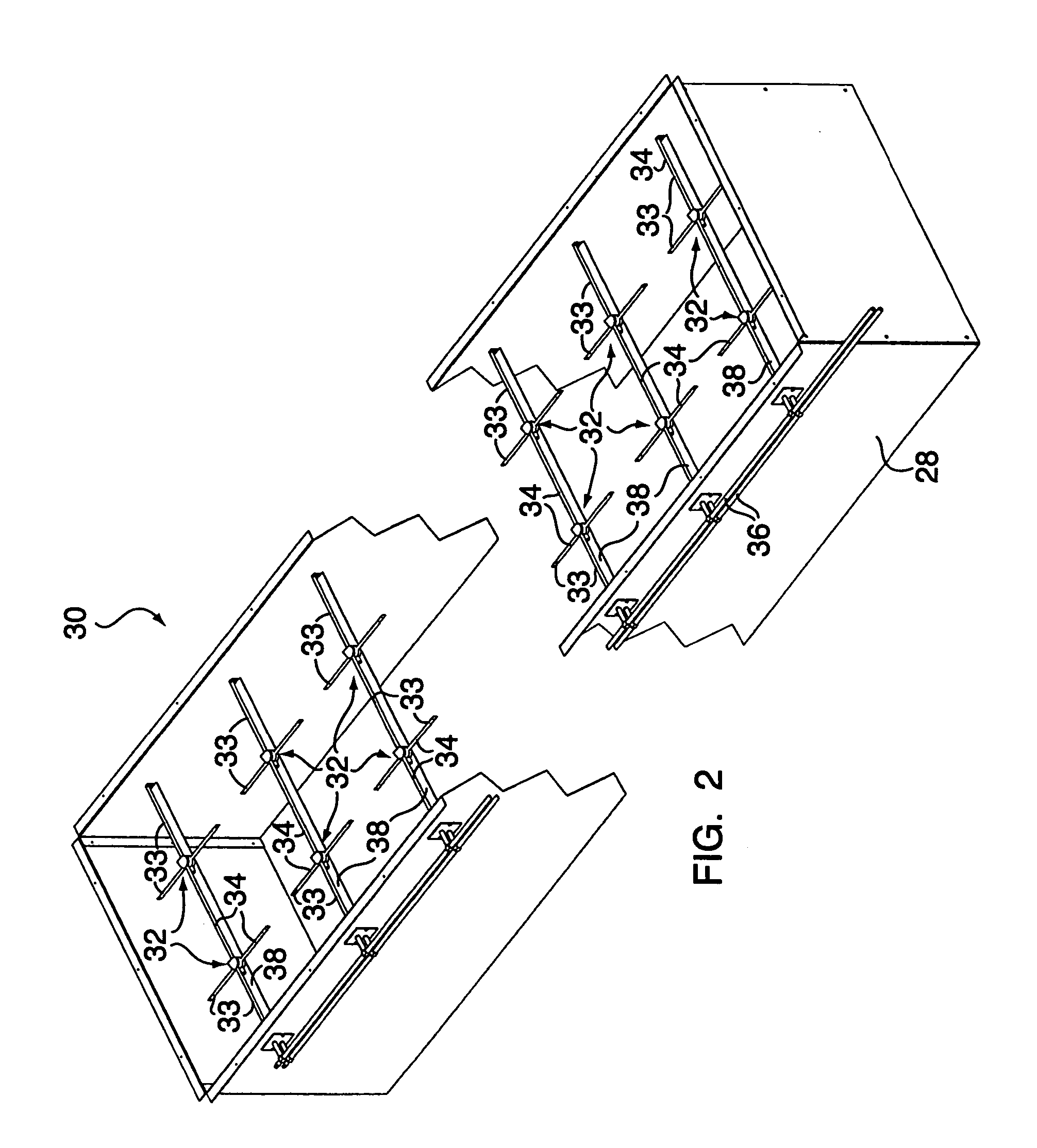
[0029]FIG. 1 is a schematic illustration of an air circulation system 10, according to one embodiment of the present invention. As shown in FIG. 1, the air circulation system 10 includes a controller 12, a heating unit 14 and a return damper apparatus 16. The heating unit 14 itself includes a gas valve 18, which selectively regulates the influx of fuel, typically hydrocarbon fuel or the like, to a burner component of the heating unit 14. In this regard, one function of the controller 12 is to control the operation of the gas valve 18, in accordance with either a manual input, automatic control, or in relation to pre-set operational parameters.

[0030]It will be readily appreciated that the controller 12 may be comprised of either a manual input keyboard and display screen, or an internalized computer and associated sub-routine, or both, without departing from the broader aspects of the present invention.

[0031]Returning to FIG. 1, an outside air-metering device 20 is utilized to provid...


PUM


Abstract

An air circulation system for use with or without ductwork having an outside air stream and a return air stream includes a controller and a return damper apparatus operatively connecting the return air stream to the controlled environment. The air circulation system further includes a heating unit and an air mass sensor disposed adjacent to the return damper apparatus. The air mass sensor selectively and directly detecting a ventilation rate of air moving through the return damper apparatus and communicates the ventilation rate to the controller which selectively modulates operation of the heating unit in dependence upon the ventilation rate.

Description

CROSS REFERENCE TO RELATED APPLICATIONS[0001]This application claims the benefit of U.S. Provisional Application Ser. No. 60 / 397,216, filed on Jul. 19, 2002, herein incorporated by reference in its entirety.FIELD OF THE INVENTION[0002]This invention relates in general to an air circulation system, and deals more particularly with an air circulation system, which controls the rise in temperature of the supply air stream relative to the amount of recirculated air in the air circulation system.BACKGROUND OF THE INVENTION[0003]Air circulation systems have become integral components in a wide variety of building applications, both residential and commercial. Typically, air circulation systems comprise a duct system in combination with a fan or blower and enable the selective, and oftentimes constant, recirculation of air. The circulation, or recirculation, of air may be utilized to promote a specific pressure regimen within the building, such as to provide a positive building pressure, o...

Claims


Application Information

Patent Timeline
Patent Type & Authority Patents(United States)
IPC IPC(8): B60H1/00F24F11/00
CPCF24F11/0001F24F11/008F24F2011/0042F24F2011/0002F24F2110/40F24F11/83
Inventor SCHNEIDER, STEPHEN M.NOVAK, ANTHONY C.
Owner MESTEK
Why Eureka
Try Eureka