
Hydrodynamic bearing, spindle motor and hard disk drive

a technology of hydrodynamic bearing and spindle motor, which is applied in the direction of sliding contact bearings, instruments, record information storage, etc., can solve the problems of reducing the useful length of bearings, reducing the stiffness of bearings, and reducing the sealing effect, so as to prevent the maxima or minima of pressure, the effect of spreading quickly and evenly

Active Publication Date: 2006-06-13
MINEBEAMITSUMI INC
View PDF8 Cites 11 Cited by
  • Summary
  • Abstract
  • Description
  • Claims
  • Application Information

AI Technical Summary

Benefits of technology

The invention provides a hydrodynamic bearing with a non-contact seal that has low power loss, high bearing stiffness, and a long lifespan. The bearing has a radial bearing section formed in the shaft and / or the cylindrical bearing sleeve. An equalizing volume is formed outside the bearing gap and connected to the bearing gap through a connecting channel / gap. The equalizing volume prevents the bearing fluid from escaping during shocks and ensures the bearing fluid is always in contact with the bearing surfaces. The invention can be used in electric motors and hard disk drives.

Problems solved by technology

The disadvantage lies in the fact that the retention capability, and thus also the sealing effect, of this concentric, tapered area diminishes due its cross-section widening towards the outside.
A further disadvantage of this known solution is that the useful length of the bearing, and consequently the bearing stiffness, is reduced by the overall axial length of such a capillary seal, i.e. the concentric, conical-shaped tapered area.
In addition, the capability of the bearing to retain the bearing oil film is reduced due to its cross-section widening at the ends of the bearing sleeve.
Another disadvantage arises from the fact that at high speeds considerable centrifugal forces are exerted on the bearing oil which could induce the bearing oil in the tapered area to rise as high as the edge of the bearing sleeve thus increasing the risk of this oil being thrown off.
One possible way of achieving this objective is by maximizing the length of the bearing, although, as outlined above, a suitably adapted capillary seal of the described art would be particularly disadvantageous in terms of overall length and thus in terms of the effective bearing length.
This consequently places severe restrictions on the dimensioning of a hydrodynamic radial bearing having sufficient stiffness and, under certain circumstances, makes it totally impossible for very small-scale spindle motors.

Method used


Image

  • Hydrodynamic bearing, spindle motor and hard disk drive
  • Hydrodynamic bearing, spindle motor and hard disk drive
  • Hydrodynamic bearing, spindle motor and hard disk drive

Examples


Embodiment Construction

[0037]In the drawings, corresponding components are indicated with the same identification reference numbers. In the illustrated embodiments, a shaft is rotatably supported in a stationary bearing sleeve. It is clear that the invention also includes designs in which a stationary shaft is enclosed by a rotatable bearing sleeve.

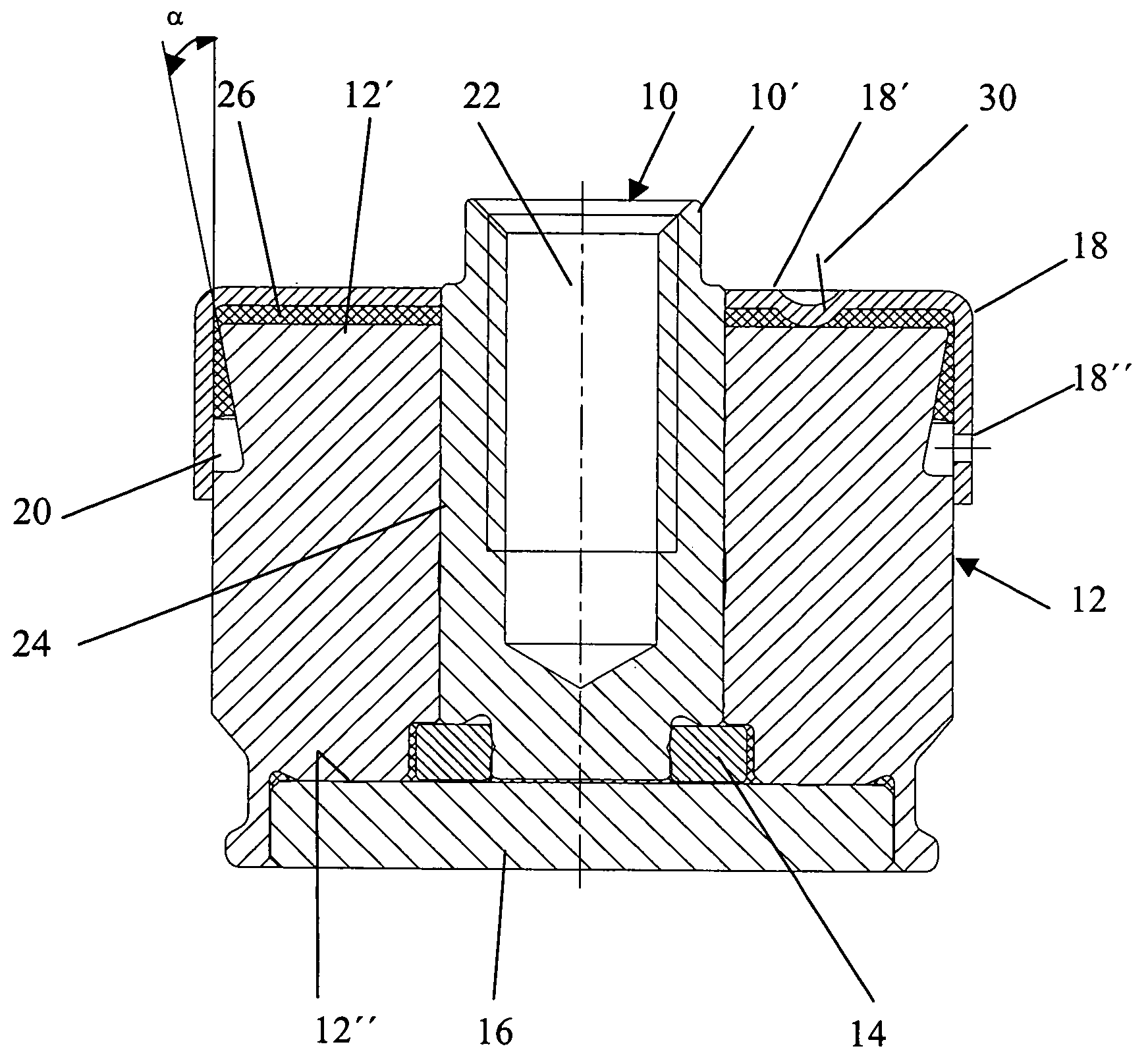
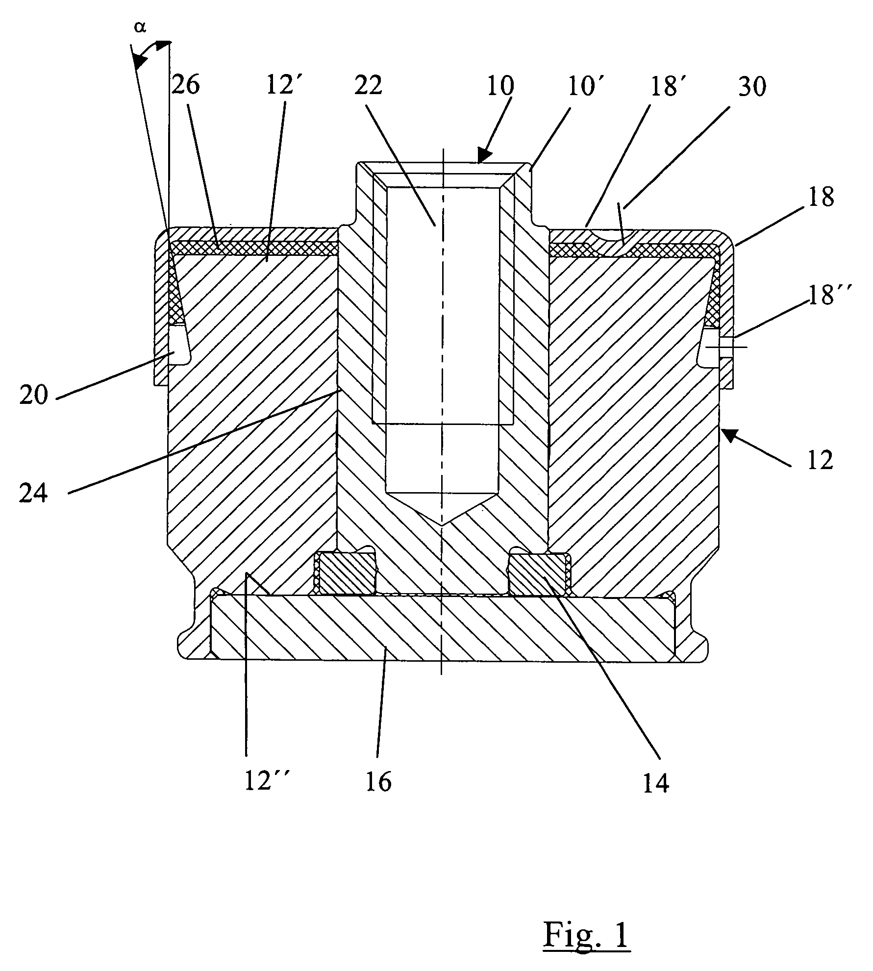
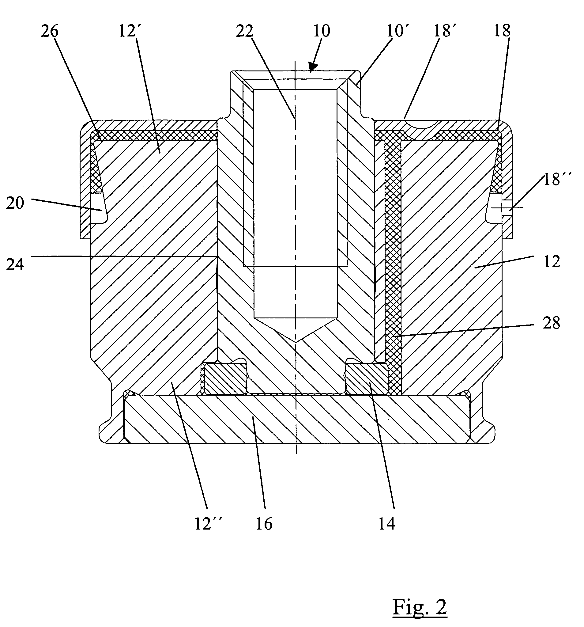
[0038]The hydrodynamic bearing shown in FIG. 1 comprises a shaft 10 which is accommodated in a cylindrical bearing sleeve 12. The shaft 10 has a thrust plate 14 at the end enclosed by the bearing sleeve 12, this end face 12″ of the bearing sleeve 12 being sealed by a counter plate 16 which takes up the axial bearing load exerted on the shaft 10 via the thrust plate 14. Both the thrust plate 14 and the counter plate 16 are accommodated in suitably dimensioned recesses in the bearing sleeve 12.

[0039]The end 10′ of the shaft 10 protrudes from the bearing sleeve 12. The bearing sleeve 12 is closed at this end by the bottom 18′ of the covering cap 18 which has a cen...


PUM

PropertyMeasurementUnit
angleaaaaaaaaaa
angleaaaaaaaaaa
widthaaaaaaaaaa

Abstract

The invention relates to a hydrodynamic bearing having a shaft, a bearing sleeve that encloses the shaft with a short radial spacing forming a concentric bearing gap, and an equalizing volume that is disposed between an outer circumference of the bearing sleeve and a covering cap at least partly overlapping the bearing sleeve and firmly fixed with respect to the bearing sleeve and connected to the bearing gap via at least one connecting channel or gap, a bearing fluid filling the bearing gap and the connecting channel / gap fully and the equalizing volume at least partially and the bearing fluid forming a continuous fluid film between the bearing gap and the equalizing volume.

Description

BACKGROUND OF THE INVENTION[0001]The invention relates to a hydrodynamic bearing, a spindle motor and a hard disk drive.OUTLINE OF THE PRIOR ART[0002]A spindle motor for a hard disk drive usually comprises a rotating component, the rotor, with which an annular permanent magnet is associated, and a stationary component, the stator, with which a lamination stack wound with coils is associated, the rotor being rotatably supported with respect to the stator by means of an appropriate bearing system.[0003]Hydrodynamic bearings are being increasingly used alongside roller bearings which have been in use for a long time. A hydrodynamic bearing is a further development on a sliding bearing, consisting of a bearing sleeve having a cylindrical inner bearing surface and a shaft having a cylindrical outer bearing surface set into the sleeve. The diameter of the shaft is slightly smaller than the inside diameter of the sleeve as a result of which a concentric bearing gap is formed between the tw...

Claims


Application Information

Patent Timeline
Patent Type & Authority Patents(United States)
IPC IPC(8): F16C17/02F16C17/10F16C33/10F16C33/74G11B19/20H02K5/167H02K7/08
CPCF16C17/107F16C33/103G11B19/2018F16C33/107F16C2370/12F16C33/745
Inventor HAFEN, MARTINHOFFMANN, JOERGBRAUN, DIETER
Owner MINEBEAMITSUMI INC
Learn More