Flame retardant, electrically conductive shielding materials and methods of making the same

a shielding material and electrically conductive technology, applied in the field of flame retardant electrically conductive emi shielding materials, can solve the problems of loss of conductivity of coated parts of fabric, interference with the operation of other electronic devices with a certain proximity, and generation of electromagnetic radiation within the electronic circuitry of equipment, so as to increase the bulk resistivity, and reduce the effect of heat generation

Active Publication Date: 2006-06-13
LAIRD TECH INC
View PDF13 Cites 37 Cited by
  • Summary
  • Abstract
  • Description
  • Claims
  • Application Information

AI Technical Summary

Benefits of technology

[0007]The present invention provides a flame retardant electrically conductive EMI shielding material which includes a porous material having internal interstices where the internal surfaces of the interstices are electrically conductive, and contain an effective amount of a flame-retardant. Preferably, the surfaces of the interstices are electrically conductive due to at least one conductive layer being disposed on internal surfaces, with a metallized layer being more preferred. Metals for the metallized layer include copper, nickel, silver, palladium, platinum, nickel-plated-silver, aluminum, tin, and alloys thereof. In one embodiment, the flame retardant is in the form of a particulate dispersed throughout the interstices of the shielding material. In this embodiment, the particulate preferably occupies no more than about 30% of the total internal surface area defined by the interstices, with no more than about 20% being more preferable, and with no more than about 10% being even more preferable. In another embodiment, the flame-retardant is in the form of a coating on the internal surfaces of the interstices. In this embodiment, the coating preferably has a thickness of about 12 microns or less, with about 5 microns or less being more preferable, and with about 2 microns or less being even more preferable. In either of these embodiments, the shielding material is preferably substantially free of occluded interstices. A preferred porous material is an open-cell foam having at least one metallized layer throughout, which can optionally include a porous scrim. An example of open-cell foam is a polyurethane foam.
[0008]The shielding materials of the invention advantageously exhibit bulk resistance and flame retardance. The shielding material preferably has a bulk resistivity of about 20 ohm·cm or less, with about 1 ohm·cm or less being more preferable, and with about 0.05 ohm·cm or less. The effective amount of flame retardant preferably provide the shielding material with at least one of following UL94 flame ratings: at least HF-1; at least HB; at least V2; at least V1; or V0. An example of a flame retardant to be used is a phosphorous-based flame retardant such as an ammonium phosphate salt. In another embodiment, the flame retardant is halogen free. The flame retardant can optionally include a polymeric carrier such as water-soluble or water-dispersible polymer. Lastly, the shielding materials of the invention preferably exhibit an average shielding effectiveness of at least about 65 decibels.
[0009]The present invention also provides a method of producing the above described shielding materials. The method includes impregnating a porous material having internal interstices, the internal surfaces of which are electrically conductive, with a flame retardant to provide an effective amount of the flame retardant on the internal surfaces of the interstices. The flame retardant is preferably in the form an aqueous composition, which can optionally include a polymeric carrier such as water-soluble or water-dispersible polymer. Preferably, the solvent for the aqueous composition is water and water-miscible organic solvents and can optionally be free of a non-water-miscible organic solvent. The method preferably includes curing the impregnated shielding material. Advantageously, the method of providing an effective amount of the flame retardant results in no more than about a 10 fold increase in bulk resistivity, with no more than a 1 fold increase in bulk resistivity being more preferable. Other preferred embodiments are as described above.
[0010]Accordingly, the present invention provides shielding materials that advantageously exhibit flame retardance and electrical properties previously unattainable. These and other advantages of the invention will be more readily apparent from the description set forth below.

Problems solved by technology

A common problem in the operation of electronic devices is the generation of electromagnetic radiation within the electronic circuitry of the equipment.
Such radiation results in “electromagnetic interference” or “EMI” and thus interferes with the operation of other electronic devices with a certain proximity.
However, the coated portions of the fabric lose conductivity due to the flame retardant coating.
Thus, while these gasket materials exhibit surface resistivity, any z-axis conductivity or bulk resistivity exhibited by these materials will be drastically diminished due to the flame retardant.

Method used


Image

  • Flame retardant, electrically conductive shielding materials and methods of making the same
  • Flame retardant, electrically conductive shielding materials and methods of making the same
  • Flame retardant, electrically conductive shielding materials and methods of making the same

Examples


example 1

[0033]Commercially available wholly metallized fabric-on-foam shielding materials were coated with undiluted Apex 911 flame retardant (viscosity of 25 cps) available from Apex Chemical Company. The fabric-on-foam shielding materials in two different thicknesses (1.0 mm and 3.2 mm) were taken from line runs of Laird Technologies fabric-on-foam products CF0040-4 and CF0125-4, respectively. 5″×11″ sheets of conductive foam were dipped in a 5″×12″ pan containing the flame retardant. The foam sheets were then nipped with a dual rubber nip roller at 10 psi. After padding, the coated foam sheets were dried in an oven at 110 degrees Celsius for approximately 25 minutes. The coated foam sheets were visually observed to be free of occluded pores. The coating weights of the Apex 911 were determined to be 4.34 opsy for the 3.2 mm material, and 1.76 opsy for the 1.0 mm material. Specimens were cut into 5″×½″ bar samples and subjected to the UTL94 Vertical Burn (V) test. The burn test results are...

example 2

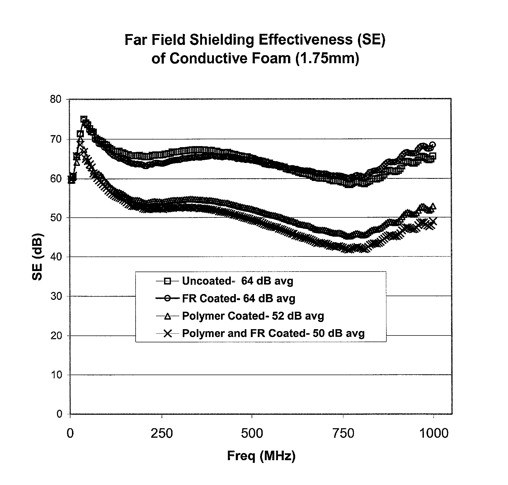
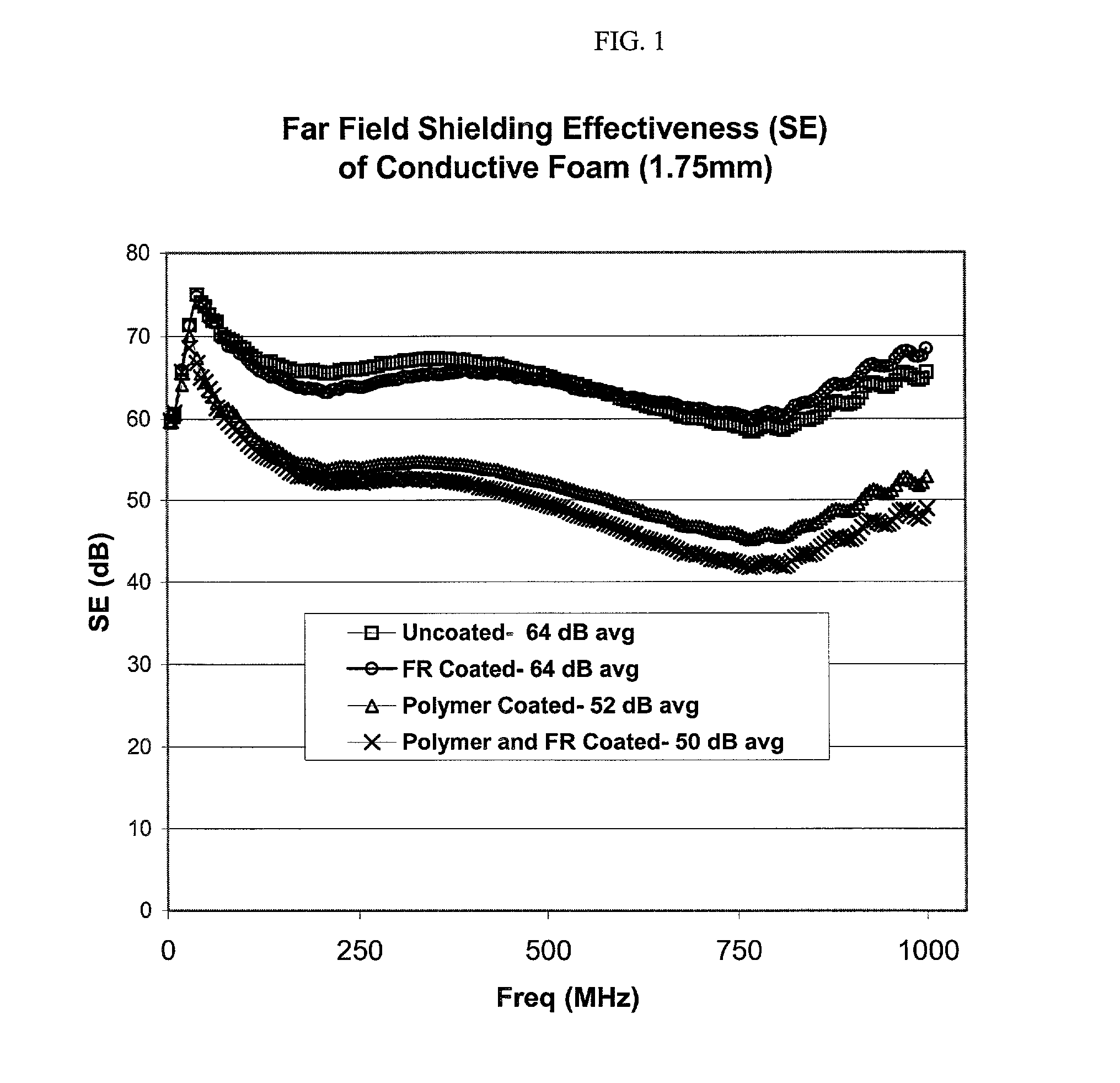
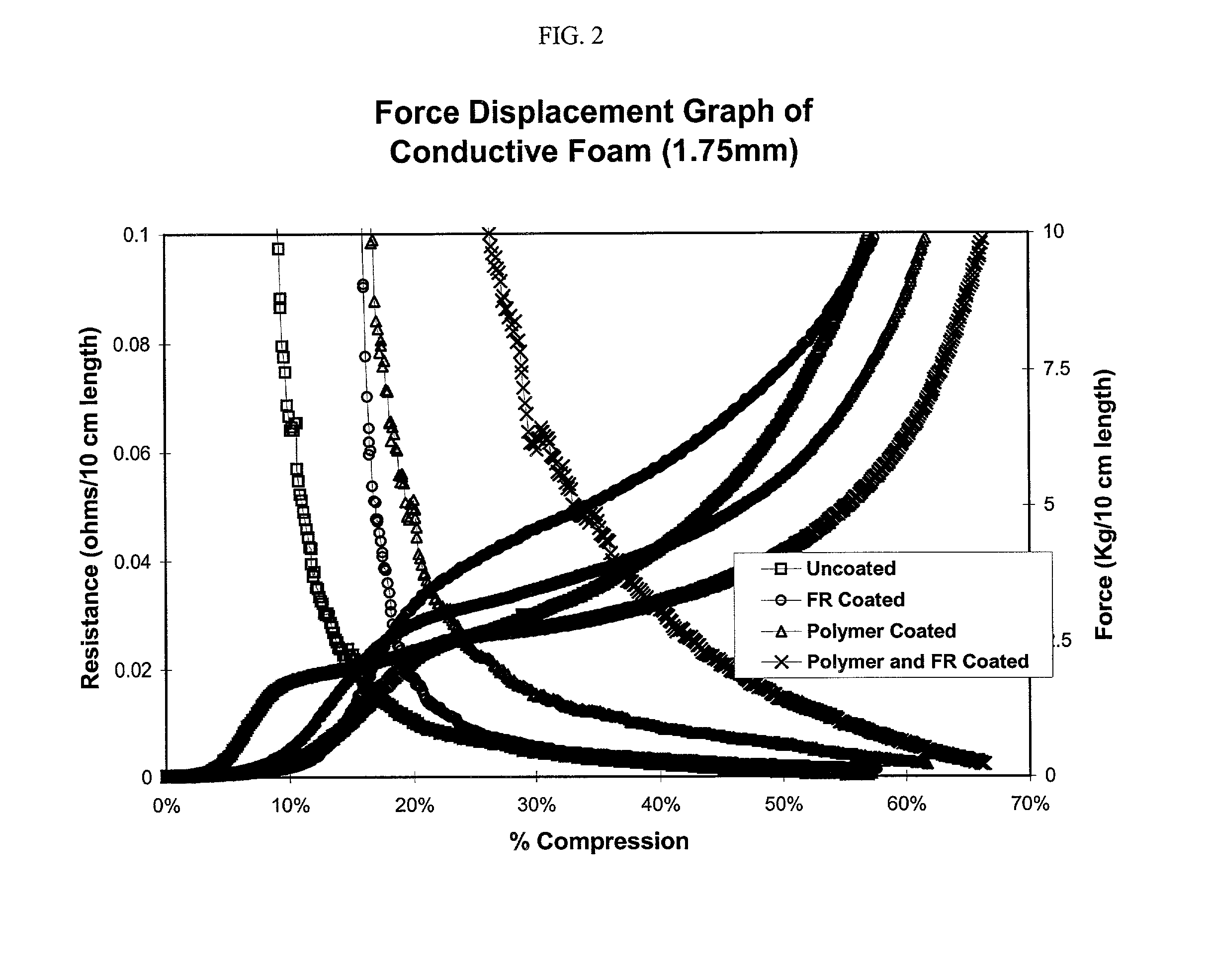
[0036]Samples of 1.75 mm thick conductive foam commercially available from Eltech Systems Corp. of Chardron, Ohio. were obtained and treated in accordance with the invention. The conductive foams were carbon coated polyurethane foam plated with 30 grams / square meter of nickel, which is sold under the product code number 2620. One group of foam samples (n=5) were not treated and served as a control. A second group of 5″×7″ sheets of conductive foam (n=5) were dipped in a 5″×12″ pan containing undiluted Flame Proof 911 coating by Apex Chemical Co and 1 weight percent (wt. %) Pentrapex 1924 (wetting agent) also available from Apex Chemical Company. The foam sheets were then nipped with a dual rubber nip roller at 10 psi. After padding, the coated foam sheets were dried at 110 degrees Celsius for approximately 25 minutes. A third group of foam samples (n=5) were first coated with a water-based urethane coating (Solucote 1024-4C by Soluol Chemical Co.). 5″×7″ sheets of conductive foam we...

example 3

[0040]Samples of a wholly conductive fabric-on-foam shielding material as in Example 1 having a thickness of 1.5 mm were impregnated with undiluted Apex 911 (with and without urethane) and with urethane alone. The material was obtained from a line run of Laird Technologies fabric-on-foam product CF0060-4. The samples of the material were impregnated following the procedure described in Example 2 with the exception that the 911 flame retardant included 0.2 wt. % Pentrapex 1924. The coated samples were visually observed to be free of occluded pores. A specimen of sample 3 (urethane coating+911 coating) was also examined under an electron microscope to evaluate the dispersed nature of the flame retardant. The internal surfaces of the pores were observed to contain an adhered particulate occupying less than 10 percent of the internal surface area. The particulate was also determined to contain a phosphorous material which correlates to the ammonium phosphate salt found in Apex 911. The ...


PUM

PropertyMeasurementUnit
thicknessaaaaaaaaaa
thicknessaaaaaaaaaa
thicknessaaaaaaaaaa

Abstract

Flame retardant EMI shielding materials with improved retention of shielding properties are disclosed. The shielding materials are provided with a dispersed flame retardant on the surfaces of the internal interstices. Methods of making the flame retardant shielding materials are also disclosed.

Description

FIELD OF THE INVENTION[0001]The present invention relates to flame retardant electrically conductive EMI shielding materials, and more particularly to flame retardant electrically conductive EMI shielding materials that exhibit improved retention of shielding properties.BACKGROUND OF THE INVENTION[0002]A common problem in the operation of electronic devices is the generation of electromagnetic radiation within the electronic circuitry of the equipment. Such radiation results in “electromagnetic interference” or “EMI” and thus interferes with the operation of other electronic devices with a certain proximity.[0003]A common solution to ameliorate the effects of EMI has been the development of shielding materials capable absorbing and / or reflecting EMI energy. These shielding materials are employed to localize EMI within its source, and to insulate other devices proximal to the EMI source. In fact, in the United States, EMI shielding materials must comply with the commercial Federal Co...

Claims


Application Information

Patent Timeline
Patent Type & Authority Patents(United States)
IPC IPC(8): B32B3/26C09K21/00H05K9/00
CPCH05K9/0084Y10T428/25Y10S428/92Y10T428/249953Y10T428/249955Y10T428/249958Y10T428/24997Y10T428/249979Y10T428/249986Y10T428/31551Y10T428/31678H05K9/00
Inventor CREASY, LARRYHUG, KEVIN
Owner LAIRD TECH INC
Why Eureka
Try Eureka