Connector terminal

a technology of connecting terminals and terminals, applied in the direction of superimposed coating process, connection contact material, liquid/solution decomposition chemical coating, etc., can solve the problems of electric wire becoming easy to be broken in the crimping section, the mechanical destruction of the surface layer at the time of fitting a connecting terminal to the base material cannot be expected, and the crimping of a connecting terminal becomes a problem. , to achieve the effect of reducing the weight of the connecting terminal,

Active Publication Date: 2012-05-10
YAZAKI CORP
View PDF12 Cites 12 Cited by
  • Summary
  • Abstract
  • Description
  • Claims
  • Application Information

AI Technical Summary

Benefits of technology

[0020]According to the invention of the above (1), because aluminum or an aluminum alloy is used as a terminal base material, the weight of the terminal can be reduced to about ⅓ the weight of a copper terminal, and this can contributes to a reduction in weight of a wire harness. Furthermore, in the case that the connector terminal of the present invention is crimped to an aluminum electric wire, the conductor of an electric wire and the terminal are the same type of a material. Therefore, decrease in crimping force by the influence of springback and influence of difference in thermal expansion can be avoided without overcrimping or crimping in two stages as in the conventional case, and as a result, both the mechanical connection performance and the electrical connection performance can be achieved. Furthermore, the presence of the Sn layer on the outermost surface of the electrical contact section can improve electrical contact reliability to a mating terminal.
[0021]In this case, because the Zn layer is provided as an underlayer of the Sn layer, the Sn layer can be formed by electroplating with good efficiency. Furthermore, because the Cu layer is interposed between the Zn layer and the Sn layer, the component element (Al) of the base material and Zn as a base diffuse in the surface of the Sn layer, and this can prevent the inherent performance of the Sn layer from being deteriorated.
[0022]That is, when Zn reaches the outermost surface and forms an oxide coating thereof, volume resistivity of an oxide of Zn is higher than that of an oxide of Sn, and this leads to an increase in contact resistance. The Cu layer functions to suppress the increase of contact resistance. An oxide of Cu has high volume resistance, leading to an increase in the contact resistance. However, diffusion rate into Sn greatly differs between Cu and Zn, and the influence of diffusion of Cu can be disregarded. Specifically, Zn causes grain boundary diffusion in Sn at very high speed, but Cu diffuses in Sn in the form of intraparticle diffusion. The intraparticle diffusion has very low speed as compared with the grain boundary diffusion. For this reason, by that the Cu layer is interposed, life-prolonging effectiveness on the practical use is obtained. However, where the Cu layer has large thickness, there is a possibility that an abso...

Problems solved by technology

Where the Sn plated layer is not present, an oxide coating of a hard copper (or copper alloy) base material appears on the surface, and as a result, mechanical destruction of the surface layer at the time of fitting a terminal to the base material cannot be expected.
In the case of using the aluminum electric wire, crimping of a terminal particula...

Method used


Image

  • Connector terminal
  • Connector terminal
  • Connector terminal

Examples


first embodiment

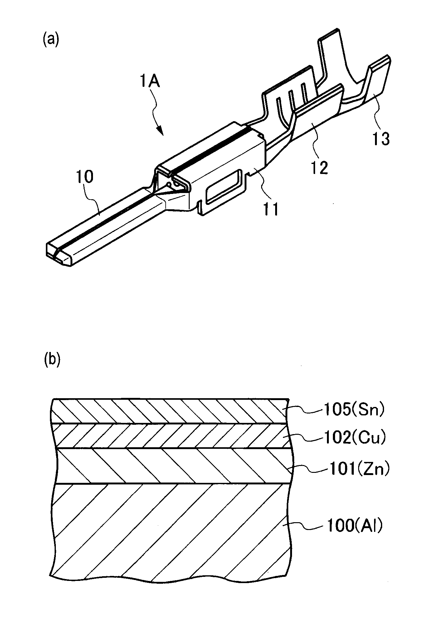
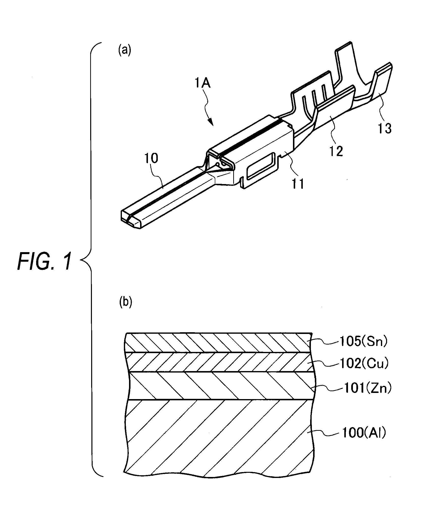
[0040]FIG. 1 shows a constitution of a connector terminal of the present invention. FIG. 1(a) is an appearance perspective view of the terminal connector, and FIG. 1(b) is a cross-sectional view showing a layer structure of a surface of a connector terminal material.

[0041]As shown in FIG. 1(a), a connector terminal 1A includes, in terms of shape, an electrical contact section 10 which is brought into contact and conducted with a mating connector terminal by fitting to the mating connector terminal, in a front section, a conductor crimping section 12 which is crimped to a conductor of an electric wire through a box section 11, in a rear side of the front section, and a covering swage section 13 swaged to an insulating cover-attached part of an electric wire, in further rear side.

[0042]In the connector terminal 1A, as shown in FIG. 1(b) and FIG. 3, metal plate materials constituting the connector terminal 1A are constituted of aluminum or an aluminum alloy as a base material 100; a Zn...

second embodiment

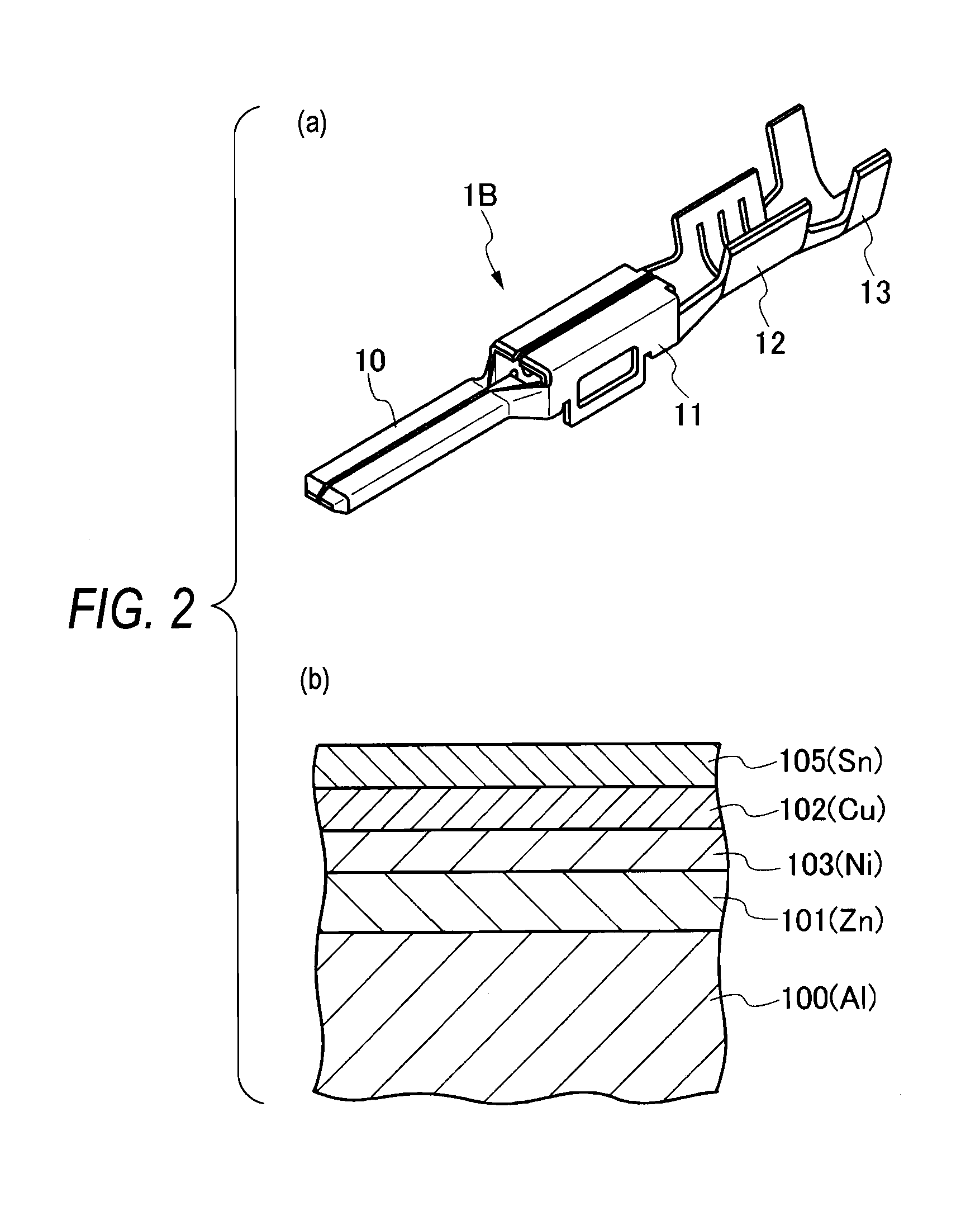
[0065]FIG. 2 shows a constitution of a connector terminal of the FIG. 2(a) is an appearance perspective view of the terminal connector, and FIG. 2(b) is a cross-sectional view showing a layer structure of a surface of a connector terminal material.

[0066]As shown in FIG. 2(a), a connector terminal 1B includes, in terms of shape, an electrical contact section 10 which is brought into contact and conducted with a mating connector terminal by fitting to the mating connector terminal, in a front section, a conductor crimping section 12 which is crimped to a conductor of an electric wire through a box section 11, in a rear side of the front section, and a covering swage section 13 swaged to an insulating cover-attached part of an electric wire, in further rear side.

[0067]In the connector terminal 1B, as shown in FIG. 2(b) and FIG. 4, metal plate materials constituting the connector terminal 1B are constituted of aluminum or an aluminum alloy as a base material 100; a Zn layer (zinc layer...


PUM

PropertyMeasurementUnit
Lengthaaaaaaaaaa
Lengthaaaaaaaaaa
Lengthaaaaaaaaaa

Abstract

A connector terminal which can achieve high mechanical connection strength and stabilized low electrical connection resistance when it is crimped to an aluminum electric wire, and in addition, can suppress electrical contact resistance low when it is fitted to a mating connector terminal is provided. In a connector terminal (1A) having an electrical contact section (10) which is brought into contact and conducted with a mating connector terminal by fitting to the mating connector terminal, and a conductor crimping section (12) which is crimped to the conductor of an electric wire, a metal material which constitutes the terminal uses aluminum or an aluminum alloy as a base material (100), a Zn layer (101) having a thickness in the range from 0.1 μm to 2.0 μm by electroless plating and a Cu layer (102) having a thickness in the range from 0.5 μm to 1.0 μm by electrolytic plating are formed in sequence on the surface of the base material (100), and an Sn layer (105) having a thickness in the range from 0.7 μm to 1.7 μm by electrolytic plating is formed on the outermost surface.

Description

FIELD OF THE INVENTION [0001]The present invention relates to a connector terminal used in a connector.BACKGROUND ART [0002]Connector terminal generally used in a connector is constituted of a metallic material including copper (Cu) or a copper (Cu) alloy, having tin (Sn) plated thereon, and has an electrical contact section which is brought into contact and conducted with a mating connector terminal by fitting to the mating connector terminal in a front section thereof and a conductor crimping section which is crimped to a conductor of an electric wire at a rear section thereof.[0003]The reason for applying Sn plating to the surface of a terminal base material is that Sn is very soft, spontaneous oxide coating of Sn can easily be mechanically destroyed by contact load between terminals in fitting connector terminals to each other, newly-formed surfaces of Sn can be contacted to each other, and as a result, good contact performance (that is, low and stabilized contact resistance) ca...

Claims


Application Information

Patent Timeline
IPC IPC(8): H01R4/18
CPCH01R4/185H01R4/62H01R13/03Y10S428/929Y10T428/12715Y10T428/12722Y10T428/12736Y10T428/12792Y10T428/1275Y10S428/935B32B15/017C25D5/12C23C28/02C23C28/021C23C28/023C23C18/1653C23C18/54C25D5/617C25D3/30C25D5/44C25D3/38
Inventor KAKUTA, NAOKI
Owner YAZAKI CORP
Why Eureka
Try Eureka