Planner inverted-F antenna having a rib-shaped radiation plate

a radiation plate and inverted antenna technology, applied in the structure of resonant antennas, protective material radiating elements, resonant antennas, etc., can solve the problems of reducing the average gain of the pifa, reducing the manufacturing cost, and easy deformation by gravity or external force. , the effect of reducing the time and the cost of manufacturing the pifa

Inactive Publication Date: 2006-06-13
SYNCOMM TECH
View PDF7 Cites 147 Cited by
  • Summary
  • Abstract
  • Description
  • Claims
  • Application Information

AI Technical Summary

Benefits of technology

[0010]It is therefore a primary objective of the claimed invention to provide a PIFA with a rib-shaped radiation plate, which has a rigidity stronger than that of a planner radiation plate, and is not deformed even after a long time of use.
[0011]Another objective of the claimed invention is to provide a PIFA with a rib-shaped radiation plate. A high temperature reflow processes of a surface mount technology (SMT) or a wave soldering process can therefore be utilized to install the PIFA onto a printed circuit board instead of a soldering process by solder iron after the high temperature reflow process. Therefore, the manufacturing time and the cost are decreased.
[0014]It is an advantage of the claimed invention that a PIFA with the rib-shaped radiation plate is not easy to be deformed by gravity or external force. Moreover, the installation of the rib does not degrade but improve the average gains of the PIFA. Further, the PIFA according to the present invention can be installed onto a printed circuit board through an SMT or a wave soldering processes, and the time and the cost of manufacturing a PIFA is therefore reduced.

Problems solved by technology

However, the sponge will melt in the environment of high temperature due to the operation of the wireless communications device.
Moreover, since the sponge cannot survive in the high temperature environment, the high temperature reflow processes of a surface mount technology (SMT) or a wave soldering process cannot be utilized to install the PIFA 10 onto a printed circuit board but a soldering process by solder iron after the high temperature reflow process.
Therefore, the manufacturing time and the cost are increased.

Method used


Image

  • Planner inverted-F antenna having a rib-shaped radiation plate
  • Planner inverted-F antenna having a rib-shaped radiation plate
  • Planner inverted-F antenna having a rib-shaped radiation plate

Examples


Embodiment Construction

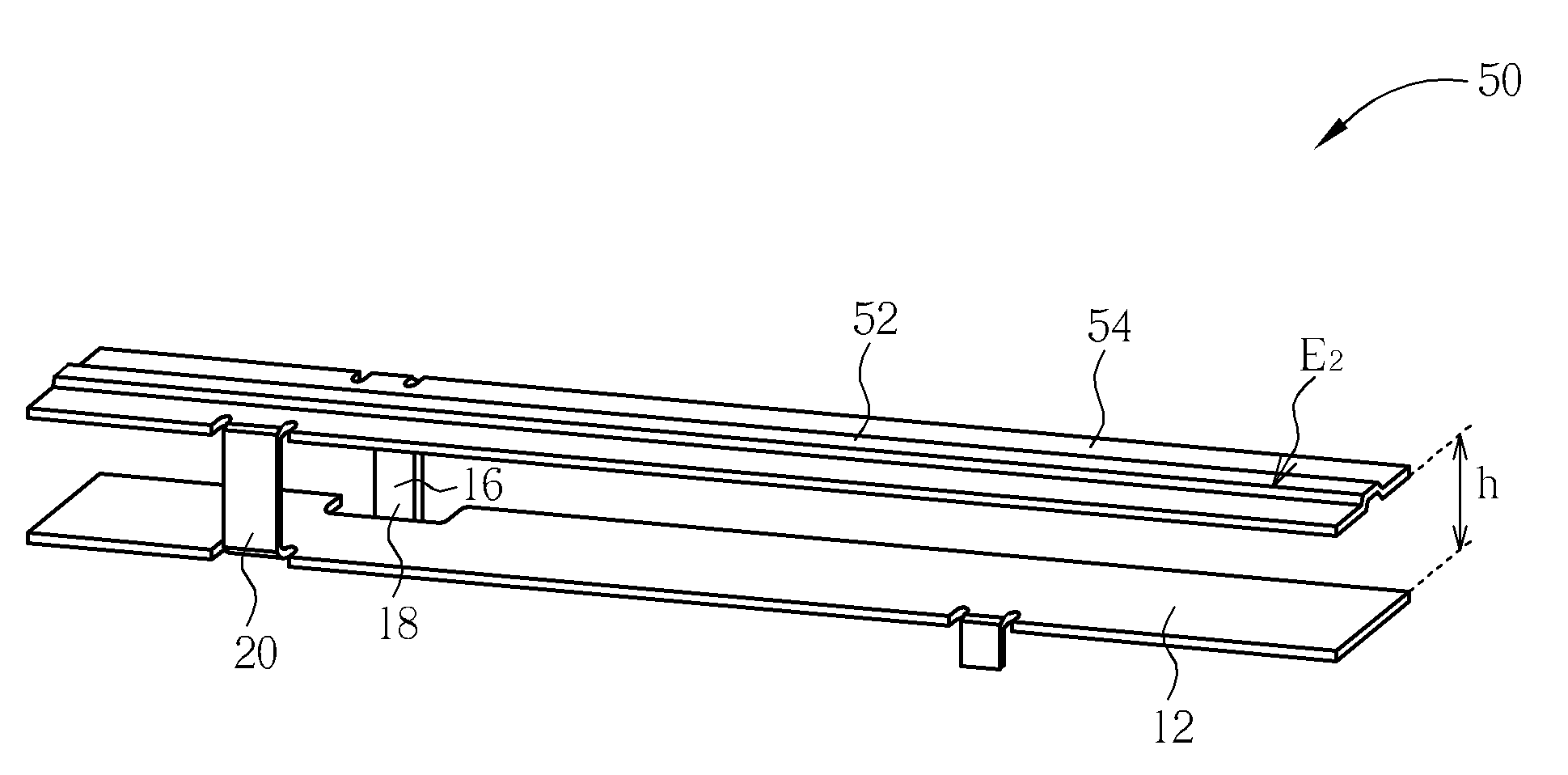
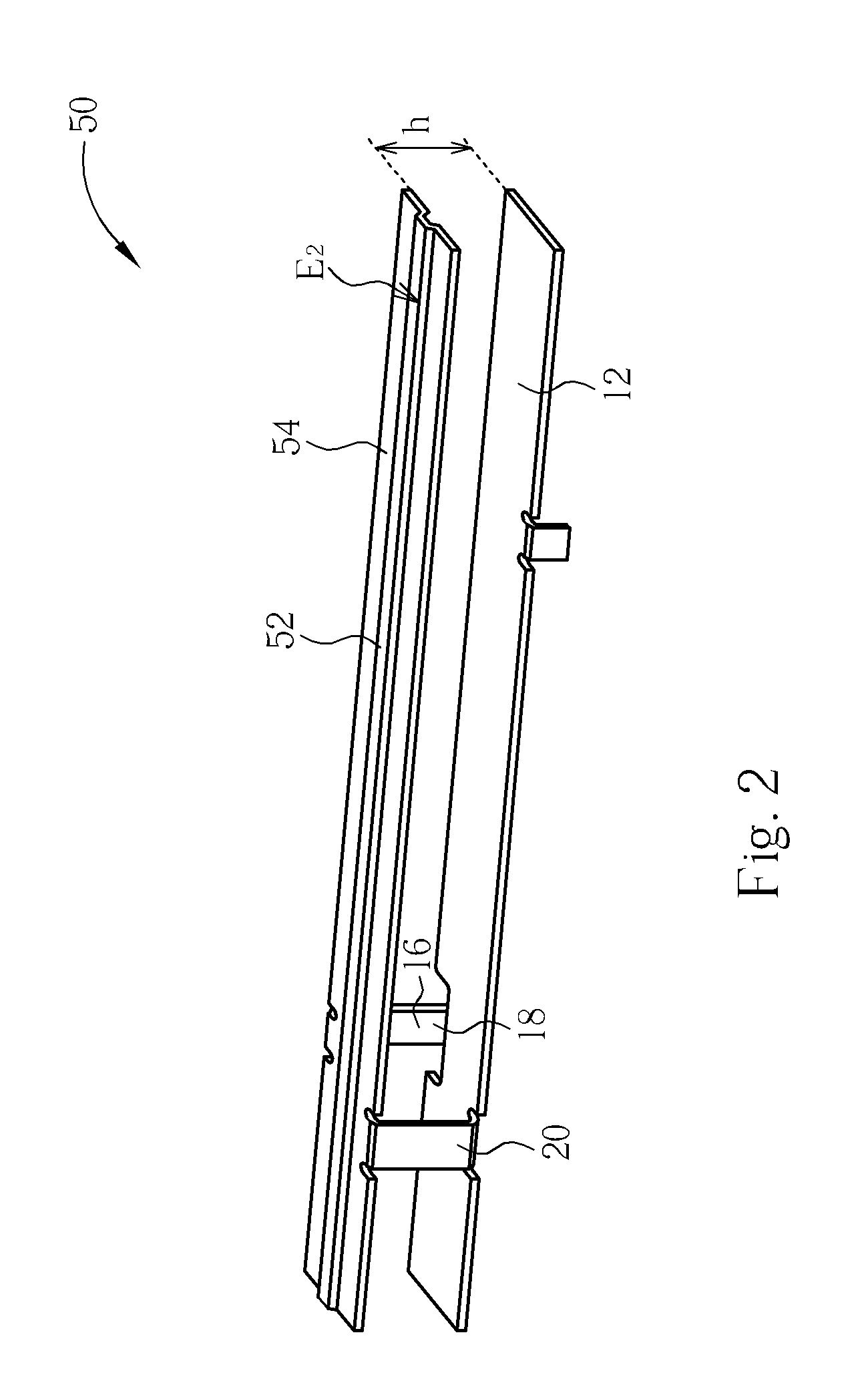
[0024]Please refer to FIG. 2, which is a schematic diagram of a PIFA 50 of the preferred embodiment according to the present invention. In addition to the ground plane 12, the feeding line 16, the feeding contact 18, and the ground contact 20, the PIFA 50 further comprises a rib-shaped radiation plate 54. In contrast with the planner radiation plate 14 described in the prior art, the rib-shaped radiation plate 54 has a non-planner structure. In detail, the rib-shaped radiation plate 54 comprises a rib 52. Through the molding of the rib 52 on the radiation plate, a better rigidity of the shaped radiation plate is performed.

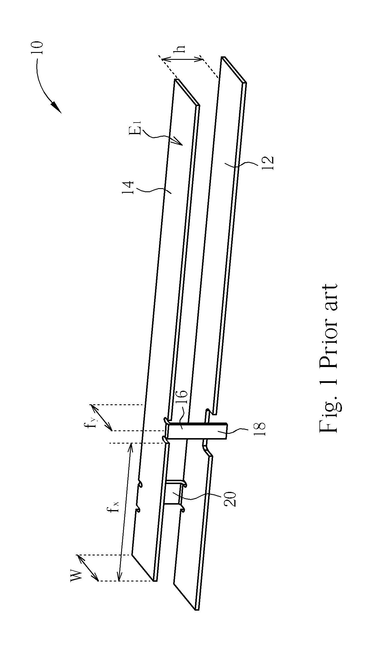
[0025]Please refer to FIG. 1 and FIG. 2. The distance h between the planner radiation plate 14 and the ground plane 12, and the distance h between the rib-shaped radiation plate 54 and the ground plane 12 are both equal to 6 mm. After an 100 gw external force is applied on an end indicated by arrow E1 of the planner radiation plate 14, as shown FIG. 3, the end of t...


PUM


Abstract

A planner inverted-F antenna (PIFA) includes a ground plane, a rib-shaped radiation plate installed approximately in parallel with the ground plane, a feeding line installed on the rib-shaped radiation plate, a feeding contact installed on an end of the feeding line, and a ground contact electrically connected to the ground plane.

Description

BACKGROUND OF INVENTION[0001]1. Field of the Invention[0002]The present invention relates to a planner inverted-F antenna (PIFA), and more particularly, to a PIFA having a rib-shaped radiation plate.[0003]2. Description of the Prior Art[0004]The quality of an antenna is very important for a wireless communication system. A desirable installation of a proper and well-designed antenna on the wireless communication device can raise the value of the signal-to-noise ratio (SNR) of wireless signals, and can improve the bit error rate (BER) of the wireless signals.[0005]Along with the development of wireless communication technologies, the integration of its device can be more and more compact. Accordingly, an embedded micro antenna has to be made as compact as possible so that can be successfully embedded into the wireless communication device. For example, a chip antenna and a planner antenna are two of the most popular micro antennas in the market. Both of the micro antennas have the ch...

Claims


Application Information

Patent Timeline
Patent Type & Authority Patents(United States)
IPC IPC(8): H01Q1/24H01Q1/40H01Q9/04
CPCH01Q9/0442H01Q9/0421
Inventor LIN, CHIN-WENLO, SHIH-CHIEHCHANG, HO-TSUNG
Owner SYNCOMM TECH
Why Eureka
Try Eureka