Liquid crystal display

Inactive Publication Date: 2006-06-13
HITACHI DISPLAYS +1
View PDF7 Cites 10 Cited by
  • Summary
  • Abstract
  • Description
  • Claims
  • Application Information

AI Technical Summary

Benefits of technology

[0011]In the case of a construction in which the electrodes of the discharge tube are disposed at the exterior thereof, it has been confirmed that the discharge effect of the discharge tube can be enhanced by increasing the width of each of the electrodes along the axial direction of the discharge tube. Accordingly, in a case where the portions of the electrodes are positioned to be superposed on an area other than the display part of the liquid crystal display panel without being bent, the width occupied by the area which makes up the picture f

Problems solved by technology

However, in the liquid crystal display device having such a construction, the life of the light source is not sufficient, and it is no exaggeration to say that the life of the liquid crystal display device is determined by the lif

Method used


Image

  • Liquid crystal display
  • Liquid crystal display
  • Liquid crystal display

Examples


Example

Embodiment 1

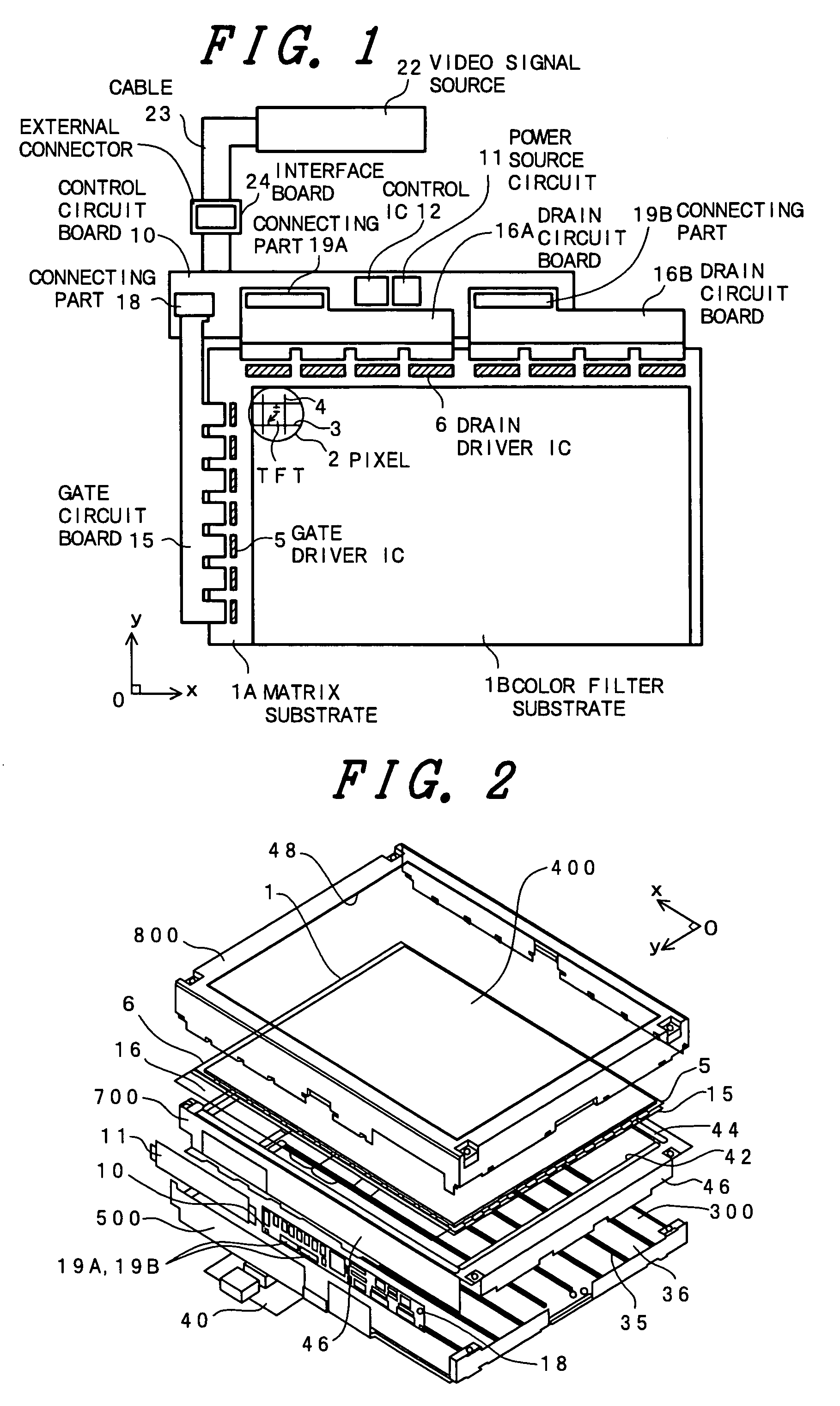
[0056]FIG. 1 is an equivalent circuit diagram showing one embodiment of a liquid crystal display panel according to the invention. FIG. 1 is a circuit diagram which is depicted to correspond to an actual geometrical arrangement of the liquid crystal display panel.

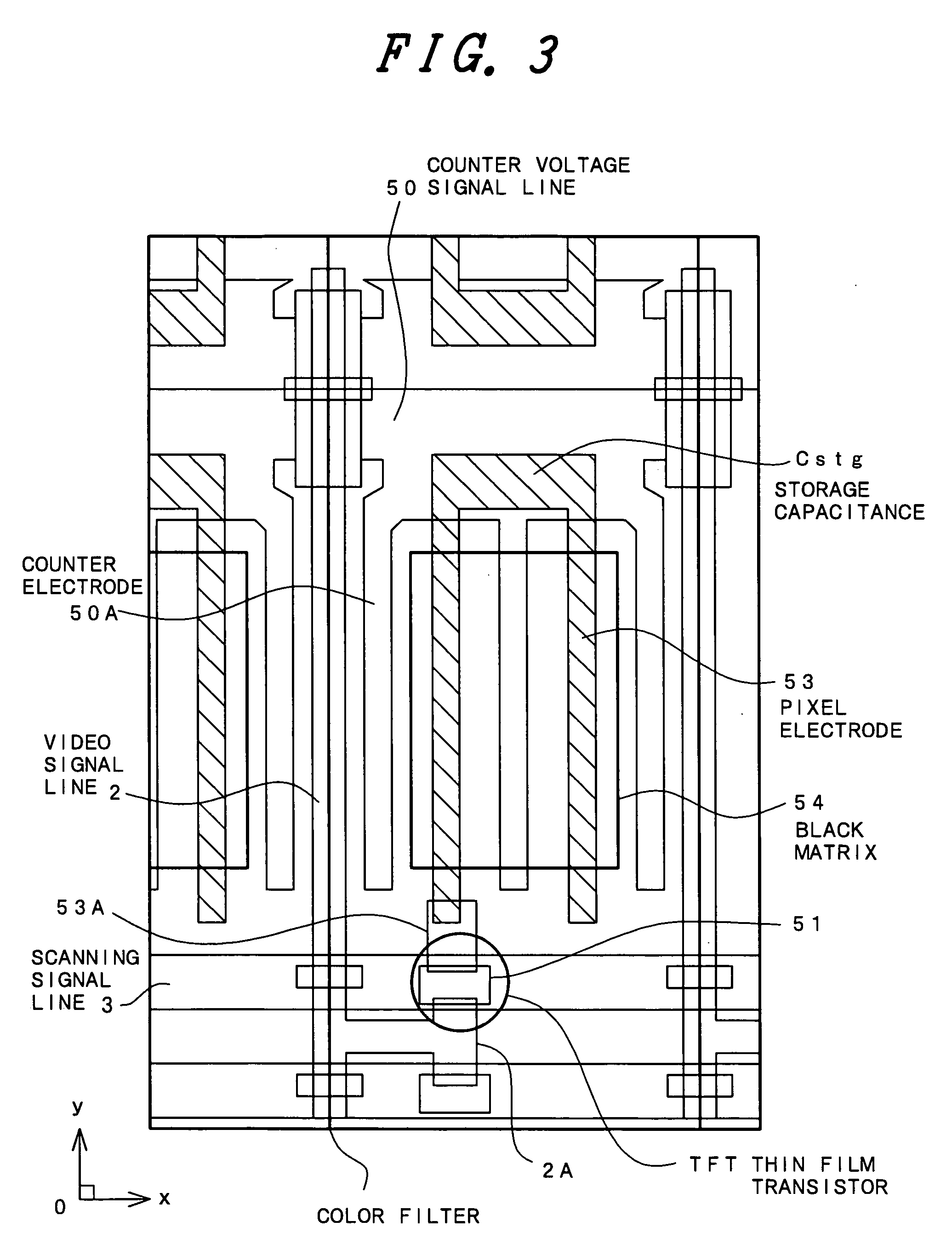
[0057]In embodiment 1, the invention is applied to a liquid crystal display device of the type which employs a so-called in-plane-switching mode, which is a known operating mode having the advantage of providing a wide viewing angle.

[0058]FIG. 1 shows a liquid crystal display panel 1 that has a pair of transparent substrates 1A and 1B disposed so as to be opposed to each other with a liquid crystal material being interposed therebetween. In this case, one of the transparent substrates (in FIG. 1, a lower substrate: the matrix substrate 1A) is formed to be slightly larger in size than the other transparent substrate (in FIG. 1, an upper substrate: the color filter substrate 1B).

[0059]As shown in FIG. 1, the trans...

Example

Embodiment 2

[0123]FIG. 13 is a cross-sectional view showing another embodiment of the liquid crystal display device according to the invention, the construction of which is improved with respect to, for example, the construction of Embodiment 1. FIG. 13 is a cross-sectional view of the assembly of the liquid crystal display device taken along the y direction (the direction perpendicular to the longitudinal direction of the light sources 35).

[0124]The construction of Embodiment 2 differs from that of Embodiment 1 in that, on the side of the backlight unit 300 that faces the liquid crystal display panel unit 400, a diffusing sheet 50 is disposed to cover the backlight unit 300, and an electromagnetic shield sheet 51 is disposed on the side of the diffusing sheet 50 that faces the liquid crystal display panel unit 400. This electromagnetic shield sheet 51 is a shield sheet for blocking electromagnetic waves generated from the light sources 35 of the backlight unit 300, and is made of, ...

Example

Embodiment 3

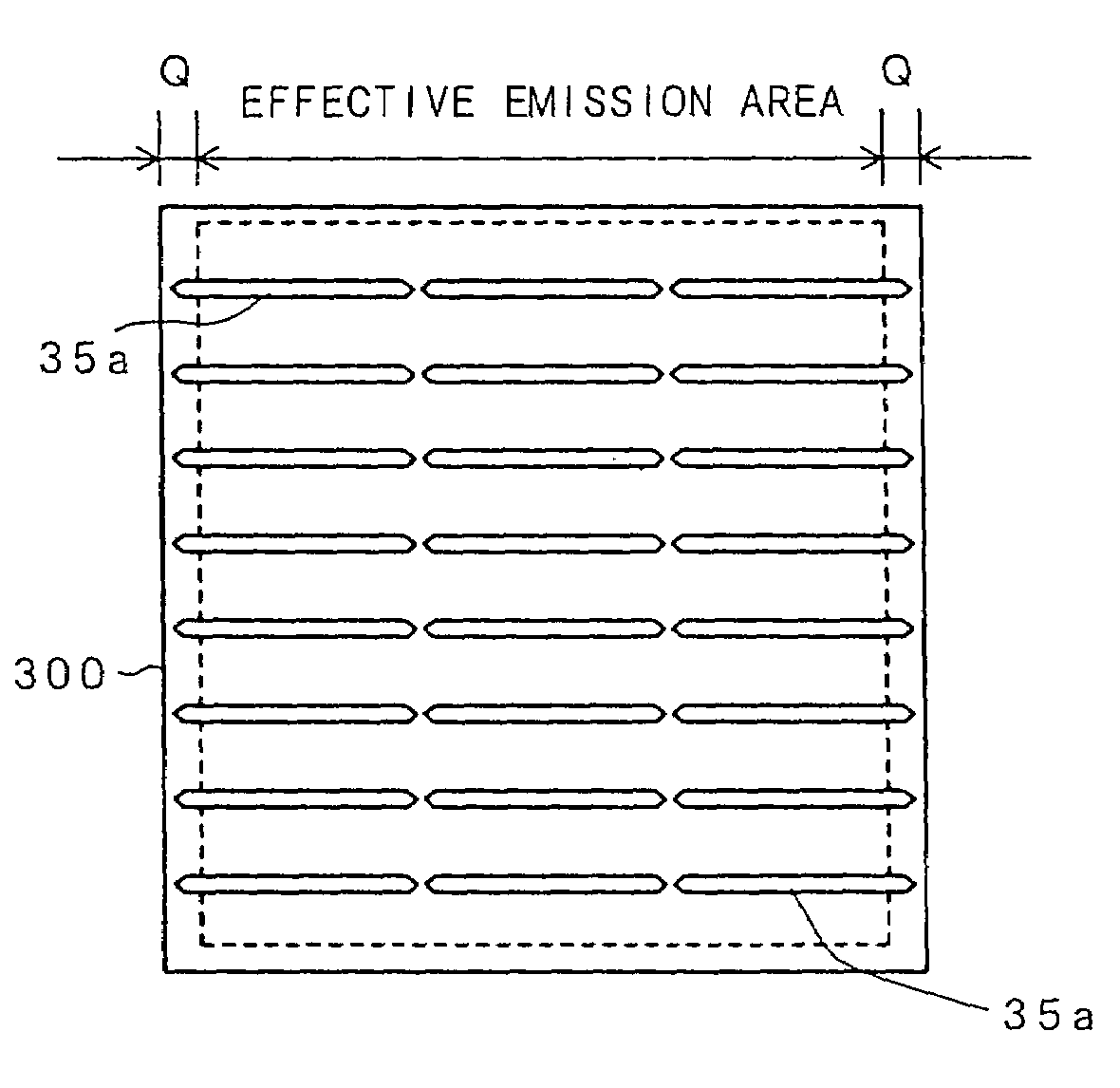
[0128]FIGS. 14A to 14C are longitudinal views showing the constructions of different modifications of each of the light sources 35 used in each of the above-described embodiments.

[0129]FIG. 14A is a view showing a modification similar to each of the light sources 35 used in each of the above-described embodiments. In the light source shown in FIG. 14A and FIG. 14A′, the electrodes have ring-like shapes, and a discharge tube is inserted through these electrodes. FIG. 14A′ is a cross-sectional view taken along line a′—a′ of FIG. 14A.

[0130]In the light source shown in FIG. 14B and FIG. 14B′, each of the electrodes is formed on part of the circumference of the discharge tube. Even with this construction, the function of the light source 35 can be similarly realized. FIG. 14B′ is a cross-sectional view taken along line b′—b′ of FIG. 14B.

[0131]In the light source shown in FIG. 14C and FIG. 14C′, the electrodes have ring-like shapes similarly to the case shown in FIG. 14A, but ...


PUM


Abstract

There is provided a liquid crystal display device having a longer useful life and in which its so-called picture frame area can be narrowed. The liquid crystal display device includes a liquid crystal display panel having a display part in its central portion and a backlight disposed on a back side of the liquid crystal display panel. The backlight includes a discharge tube having electrodes at least at its opposite ends, and the electrodes are disposed at the exterior of the discharge tube. The opposite end portions of the discharge tube where the respective electrodes are disposed are positioned to be superposed on the periphery of the liquid crystal display panel and are bent with an angle with respect to the central axis of the discharge tube.

Description

BACKGROUND OF THE INVENTION[0001]The present invention relates to a liquid crystal display device; and, more particularly, the invention relates to a liquid crystal display device including a liquid crystal display panel and a back light disposed on the back side of the liquid crystal display panel.[0002]A liquid crystal display device typically includes a panel made of transparent substrates disposed so as to be opposed to each other with a liquid crystal material interposed therebetween, and multiple pixels are formed in the area of the liquid crystal material. In this case, each of the pixels only has the function of controlling the amount of light being transmitted through the liquid crystal material, and does not itself emit light. For this reason, ordinarily, a backlight is disposed on the back side of the liquid crystal display panel.[0003]This backlight is provided with not only a light source, but also a diffusing sheet and a reflector in order to cause the irradiation of l...

Claims


Application Information

Patent Timeline
IPC IPC(8): G09G3/36G02F1/1335G09G3/00F21V8/00G02F1/13357G09F9/00
CPCG02B6/0071G02B6/009H01J65/046G02F1/133604G02B6/0083G02F1/133605G02F2001/133613G02F1/133613G02F1/1335
Inventor YAJIMA, TOSHIHIRONISHIYAMA, SEIICHITAKAKU, SHIGETAKENOGUCHI, SHOICHITAKEDA, YOSHIHARU
Owner HITACHI DISPLAYS
Why Eureka
Try Eureka