
Method to project electronics from load dump

a technology of load dump and electronics, applied in the direction of emergency protective arrangements for limiting excess voltage/current, electrical devices, emergency protective arrangements, etc., can solve problems such as detection of load dump events, and achieve the effects of consuming excess transient energy, and preventing damage to an ecu

Active Publication Date: 2006-06-13
INFINEON TECH AMERICAS CORP
View PDF5 Cites 1 Cited by
  • Summary
  • Abstract
  • Description
  • Claims
  • Application Information

AI Technical Summary

Benefits of technology

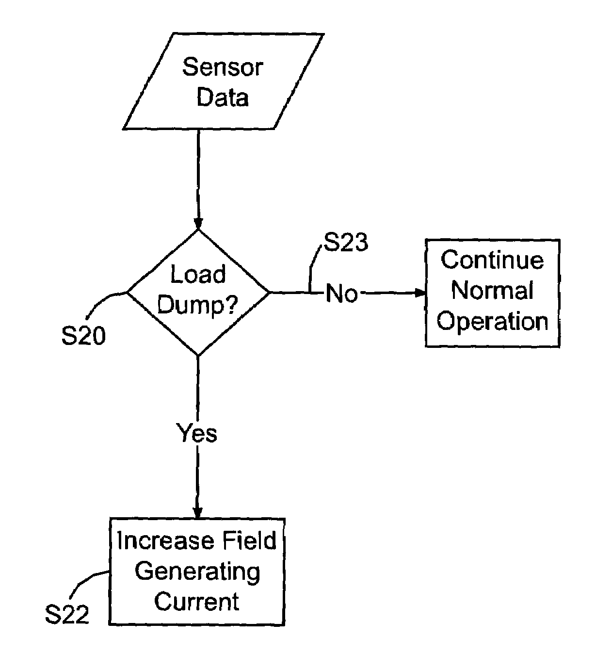
[0020]According to the present invention, to prevent damage to an electronic circuit due to a load dump the load dump event is detected and, in response to the detected load dump event the excess transient current is consumed by a device within the system.
[0022]According to the first embodiment of the present invention, in order to prevent damage to an ECU which may result from load dump the motor which is connected and controlled by the ECU is driven into saturation. Specifically, according to the first embodiment of the present invention, the current for generating the magnetic field in the motor is increased to drive the motor into saturation to cause the motor to operate inefficiently in order to consume the excess transient energy.
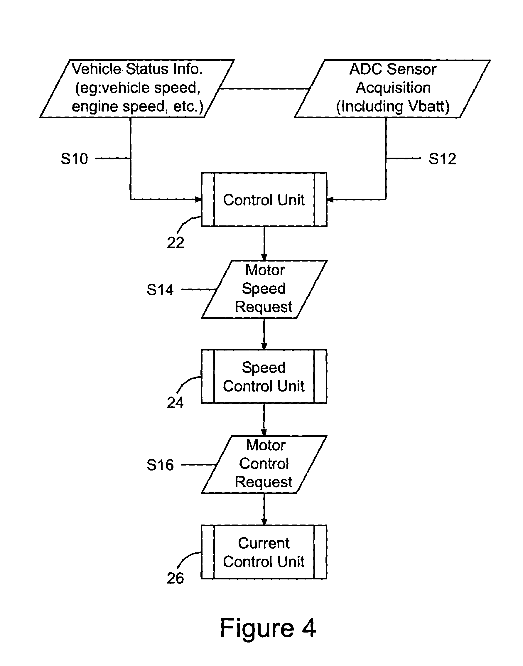
[0023]According to the second embodiment of the present invention, in order to prevent damage to an ECU which may result from load dump, the energy generated due to load dump is directed to and consumed by an electro-mechanical device. For example, the speed of the motor connected to the ECU is allowed to increase in order to consume the excess transient energy.

Problems solved by technology

Second, a load dump event is detected when the voltage output from the battery reaches a predetermined maximum value.

Method used


Image

  • Method to project electronics from load dump
  • Method to project electronics from load dump
  • Method to project electronics from load dump

Examples


first embodiment

[0035]According to the present invention, damage to an ECU due to a load dump event may be prevented by increasing the iron losses in the motor that is controlled by the ECU in a controlled manner to cause the consumption of the excess transient energy until a safe voltage value is reached.

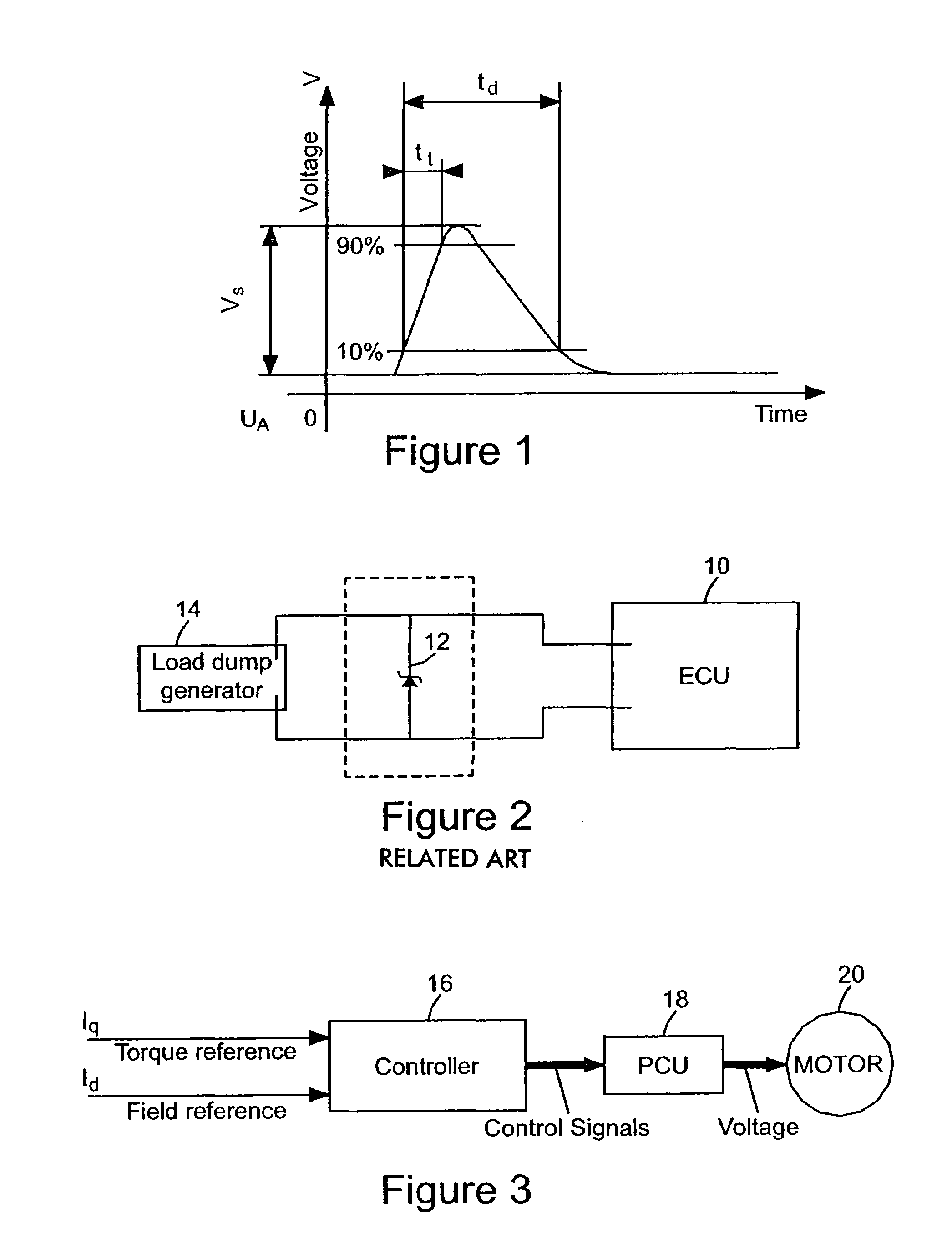
[0036]FIG. 3 shows a functional block diagram for a known motor control technique in which the motor is magnetic field generating current and torque generating current are separately controlled. The motor control technique shown by FIG. 3 includes controller 16 which is operatively connected to power circuit unit (PCU) 18. PCU 18 may be comprised of power switching devices such as MOSFETs or IGBTs in a half-bridge, full bridge configuration or some other configuration. Controller 16 sends control signals to the power switching devices of PCU 18 in order to control the operation of motor 20, such as its speed, by controlling the voltage supplied thereto. Controller 16 shown by FIG. 3 controls the f...

second embodiment

[0045]In a system devised according to the present invention the increased torque output, which normally results in increased speed, must be tolerated by the specific application. Therefore, a trade-off between the voltage reduction and the speed increase may be necessary.

[0046]As is clear from the above, to implement a method according to the present invention, a load dump event must be first detected. The input voltage in a conventional system is monitored to enable the unit to shutdown in either over-voltage or under-voltage conditions. The load dump detection algorithm must be able to distinguish between normal over-voltage and a load dump event. According to one aspect of the present invention, to distinguish between normal over-voltage events and a load dump event the voltage of the battery is monitored over time. If the increment between two consecutive voltage samples is greater than 0.5V the micro-controller enters a load dump mode, in which it remains until the voltage rea...


PUM


Abstract

A method for averting damage that may be caused by a transient energy surge during a load dump event, the method including detecting the load dump event and in response causing the consumption of transient excess energy due to the load dump event.

Description

RELATED APPLICATION[0001]The application is based on and claims benefit of U.S. Provisional Application No. 60 / 369,384, filed Apr. 1, 2002, entitled METHOD TO PROTECT ELECTRONICS FROM LOAD DUMP USING MOTOR, to which a claim of priority is made.BACKGROUND OF THE INVENTION[0002]Most automotive power electronics systems must comply with standards for transient immunity. One such standard is ISO 7637-1. ISO 7637-1 is an over voltage protection standard.[0003]FIG. 1 shows a simulation of a transient condition which occurs when the car battery is disconnected while the car alternator is generating charging current and the loads remain connected to the alternator. The transient condition shown by FIG. 1 is conventionally referred to as a load dump event. Load dump may occur due to a fortuitous event such as battery cable corrosion, poor cable connection or the disconnection of the battery while the engine is running.[0004]The amplitude of a load dump transient pulse depends on the alternat...

Claims


Application Information

Patent Timeline
Patent Type & Authority Patents(United States)
IPC IPC(8): H02H7/09H02H7/06H02H9/04
CPCH02H9/04H02H7/067
Inventor GORGERINO, ANDREAJENSEN, KLAUS S
Owner INFINEON TECH AMERICAS CORP
Learn More