
Directional hearing aid tester

a hearing aid and directional technology, applied in the direction of material solid analysis using sonic/ultrasonic/infrasonic waves, instruments, etc., can solve the problem of impracticality for most hearing aid dispensers to use, rear-facing responses will introduce significant errors, and use of anechoic test space presents additional problems. to achieve the effect of accurate testing of the directional response of a hearing aid

Active Publication Date: 2006-06-13
RHINOMETRICS
View PDF2 Cites 13 Cited by
  • Summary
  • Abstract
  • Description
  • Claims
  • Application Information

AI Technical Summary

Benefits of technology

[0005]Accordingly, it is an object of the invention to provide a method and apparatus for more accurately testing the directional-response of a hearing aid, even if the hearing aid has level-dependent signal processing circuitry.

Problems solved by technology

Because the non-linear circuitry often causes both the gain and the frequency response of the hearing aid to be level-dependent, it is not possible to measure an accurate directional response by using (for example) two sound sources, one front-facing (i.e. in front of the hearing aid) and the other rear-facing (i.e. facing the rear of the hearing aid), and separately in time sweeping them through various frequencies.
As mentioned, measuring the front-facing and rear-facing responses separately will introduce significant error if the hearing aid has level-dependent gain and frequency shaping circuitry that responds to the overall input level.
Using an anechoic test space presents additional problems.
Such space must be large and filled with sound absorbing material to prevent standing waves, and this makes it impractical for use by most hearing aid dispensers.
In addition, the responses measured in an anechoic chamber do not accurately reflect the real world performance that might be expected in a typical hard-walled room such as in a home or office environment where standing waves are present.
It has not previously been possible to assess the performance of a directional microphone system in a real world echoic environment because it has not been possible to present appropriate front-facing and rear-facing signals simultaneously.

Method used


Image

  • Directional hearing aid tester
  • Directional hearing aid tester
  • Directional hearing aid tester

Examples


Embodiment Construction

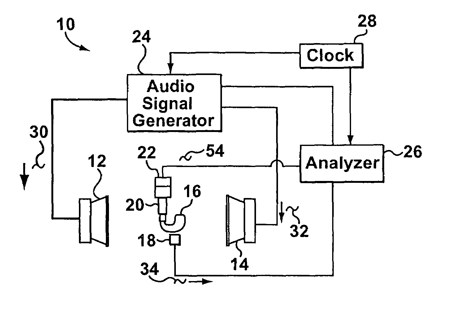
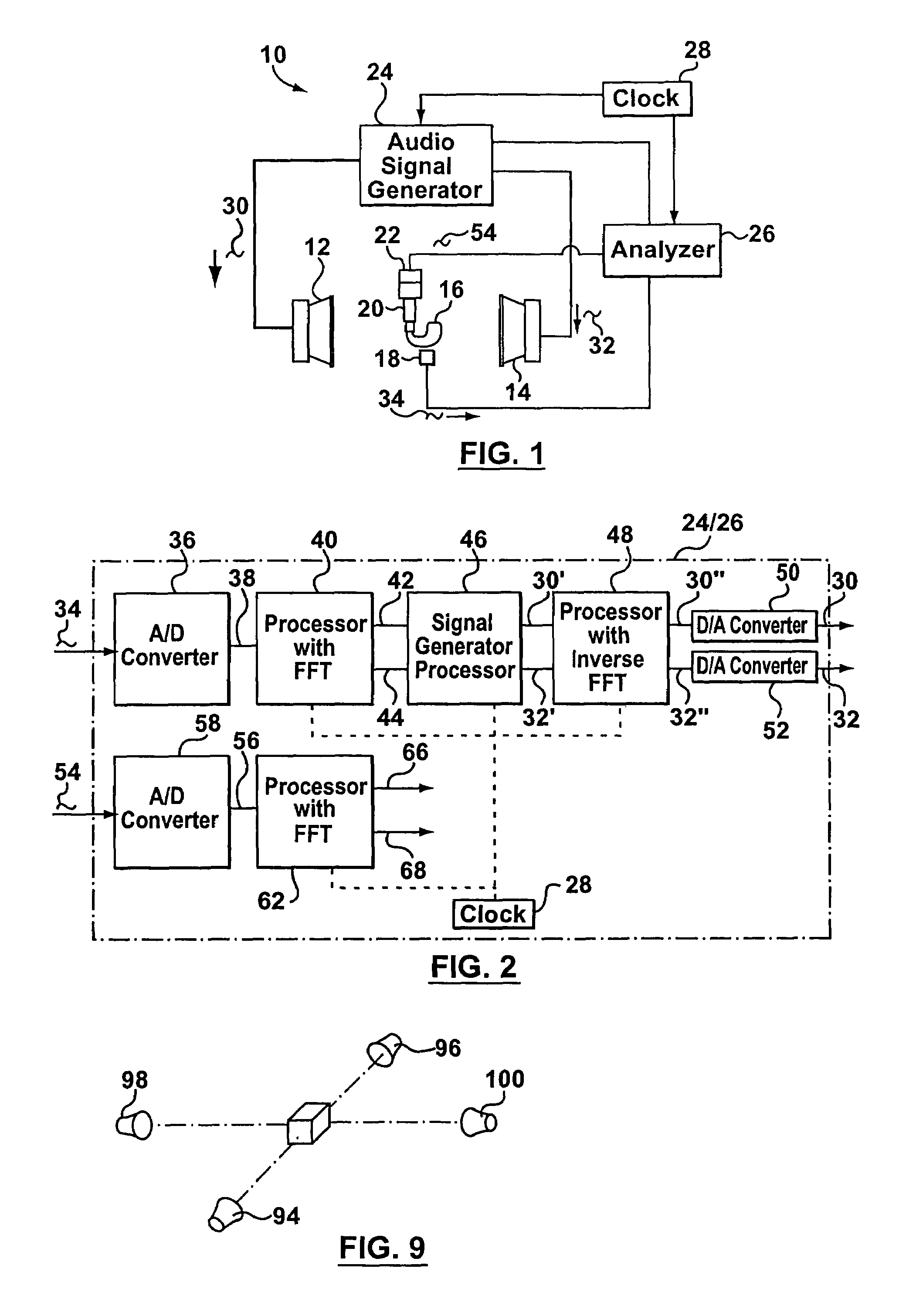
[0027]The preferred embodiment of the invention will be described with reference to testing a directional hearing aid. However, the method and apparatus of the invention may be used with other directional-responding acoustical devices, e.g. microphones, and sound recorders for various applications.

[0028]As shown in FIG. 1, a test space 10, which can be either an acoustically-treated anechoic space or a non-treated echoic space, contains two spaced apart loudspeakers, namely a first speaker 12 and a second speaker 14. The two loudspeakers are shown as being in the same plane and facing each other, but this configuration is arbitrary and depends on the performance characteristic which is desired to be measured.

[0029]The hearing aid 16 to be tested is shown midway between the loudspeakers 12, 14, but the hearing aid 16 can be placed in any desired orientation. Located closely adjacent the hearing aid 16 are a controlling microphone 18 (used for a purpose to be explained), a conventiona...


PUM


Abstract

Method and apparatus for testing a directional acoustic device such as a directional hearing aid having level-dependent non-linear circuitry, in which two or more speakers are placed at desired positions relative to the hearing aid, e.g. in front and behind the hearing aid. The speakers are excited simultaneously with broadband excitation signals formed from components which are orthogonal to each other, e.g. sinusoids, where the bin frequencies of the Direct Fourier Transform (“DFT”) of one excitation signal are different from the bin frequencies of the other excitation signal. Thus, the response to each excitation signal can easily be extracted without filtering, allowing the directional characteristics of the hearing aid to be evaluated.

Description

FIELD OF THE INVENTION[0001]This invention relates to apparatus and methods for testing directional responding acoustical devices to determine their response to sound stimuli. The directional responding acoustical devices will usually, although not necessarily, be directional hearing aids.BACKGROUND OF THE INVENTION[0002]Hearing aids are tested by supplying a known acoustical test stimulus to the hearing aid microphone and measuring the resulting output. Increasingly, modern hearing aids employ a combination of directional responding microphones and non-linear signal processing to provide better performance to the end-user. Because the non-linear circuitry often causes both the gain and the frequency response of the hearing aid to be level-dependent, it is not possible to measure an accurate directional response by using (for example) two sound sources, one front-facing (i.e. in front of the hearing aid) and the other rear-facing (i.e. facing the rear of the hearing aid), and separa...

Claims


Application Information

Patent Timeline
Patent Type & Authority Patents(United States)
IPC IPC(8): H04R29/00H04R25/00
CPCH04R25/30H04R29/004H04R25/40
Inventor JONKMAN, JACOBUS
Owner RHINOMETRICS
Learn More