Cleaning apparatus, image forming apparatus, and process cartridge

a technology of cleaning apparatus and process cartridge, which is applied in the direction of electrographic process apparatus, instruments, optics, etc., can solve the problems of insufficient cleaning of cleaning apparatus using electrostatic method, inability to improve image quality, and affecting the cleaning effect, so as to reduce friction

Inactive Publication Date: 2006-06-13
RICOH KK
View PDF66 Cites 29 Cited by
  • Summary
  • Abstract
  • Description
  • Claims
  • Application Information

AI Technical Summary

Benefits of technology

[0026]According to an embodiment of the present invention, at least a portion of the rubber plate member may be surface treated for reducing friction created thereon.

Problems solved by technology

However, the cleaning apparatus using the electrostatic method is unable to clean sufficiently since the cleaning apparatus relies on the polarity of the toner after transfer, and is largely influenced by environmental factors such as temperature and humidity.
Accordingly, image quality cannot be improved with this method.
Nevertheless, as the diameters of the toner particles become smaller and as the shapes of the toner particles become closer to a sphere, cleaning tends to become more difficult.
More specifically, after a toner image is transferred to a target transfer body, it is difficult to sufficiently remove toner remaining on the surface of the image carrier, and thereby results in poor cleaning performance.
Since toner, being situated at a contacting part between the image carrier and the cleaning blade, is more or less near a closest packed state during cleaning with a blade cleaning method, a first layer of toner, which is situated toward the image carrier side and which firmly adheres to the image carrier, slides against a second layer of toner situated above the first layer of toner, thereby causing the toner of the first layer to remain on the image carrier and resulting in poor cleaning performance.
These, however, promote the wear of the image carrier and accelerate the wear of the rubber of the blade, thereby shortening the longevity of the cleaning blade.
A conventional cleaning process employing a cleaning blade for cleaning remaining toner faces problems such as turning over of the cleaning blade, generation of abnormal noise, and accelerated wear of the cleaning blade.
Furthermore, the conventional cleaning process faces a problem of a filming phenomenon in which the blade member and the image carrier rubbing against each other causes resin material of toner to adhere to the surface of the image carrier.
This results in degrading of image quality.
This method, however, faces a problem of wearing of the cleaning blade at a portion that rubs against the image carrier.
That is, as in Japanese Patent Registration No. 02961926, since the components of the cleaning apparatus are all adhered to each other with an adhesive agent, the unit for replacing a worn cleaning blade would include other components adhered to the cleaning blade, to thereby increase cost.
Furthermore, the example shown in Japanese Laid-Open Patent Application No. 9-325659, which has a plate spring member serving as an elastic member, is also unable to reduce cost, since the unit for replacing a worn cleaning would include the plate spring member.
Furthermore, in a case where a piezoelectric element, serving as a vibration source, is provided to the cleaning blade, the replacement of the cleaning blade requires further cost due to the additional cost of replacing the piezoelectric element.
Particularly, when the piezoelectric element is still able to be used, the replacement of the cleaning blade is wasteful.
Meanwhile, in the example shown in Japanese Laid-Open Patent Application No. 2000-259051, since resin is coated on the surface of the cleaning blade by using a CVD method, an adhering property (effect) of rubber itself is reduced, to thereby degrade cleaning performance.
Furthermore, the example has a problem of lacking endurance since the rubbing between the cleaning blade and the image carrier causes the coating on the blade surface to peel off.
This causes creation of a gap therebetween, and results in poor cleaning performance.
Furthermore, since the image carrier itself is formed of a resin mainly composed of polycarbonate, problems such as damaging of the surface therebetween are caused.
This causes difficulty in obtaining a steady vibration.
Furthermore, this example requires a considerably large vibrator for uniformly forming standing waves in a width direction of the image carrier, therefore making size reduction of the apparatus difficult.
Furthermore, efficiency in the propagation of vibration is extremely poor since the material of the cleaning blade is an elastic material.
Furthermore, since the vibration is applied in a longitudinal direction of the cleaning blade, the propagation of vibration is absorbed, thereby resulting in poor vibration efficiency.

Method used


Image

  • Cleaning apparatus, image forming apparatus, and process cartridge
  • Cleaning apparatus, image forming apparatus, and process cartridge
  • Cleaning apparatus, image forming apparatus, and process cartridge

Examples


first embodiment

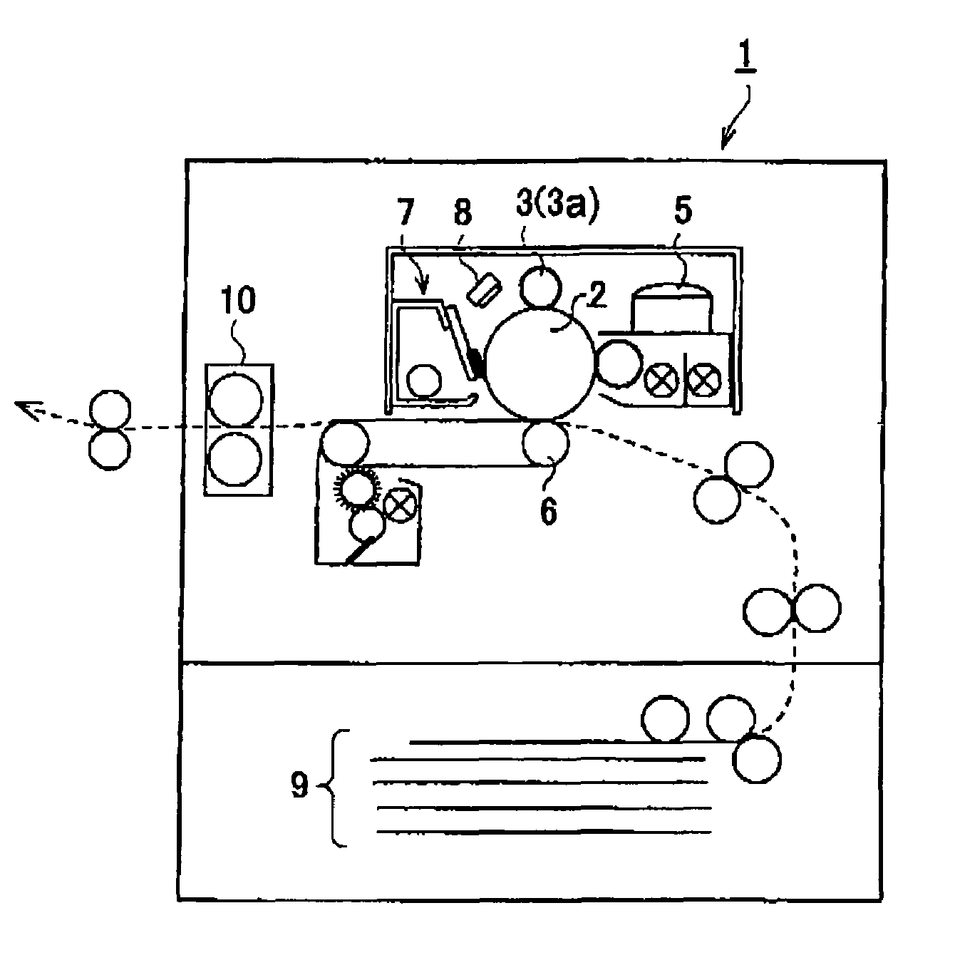
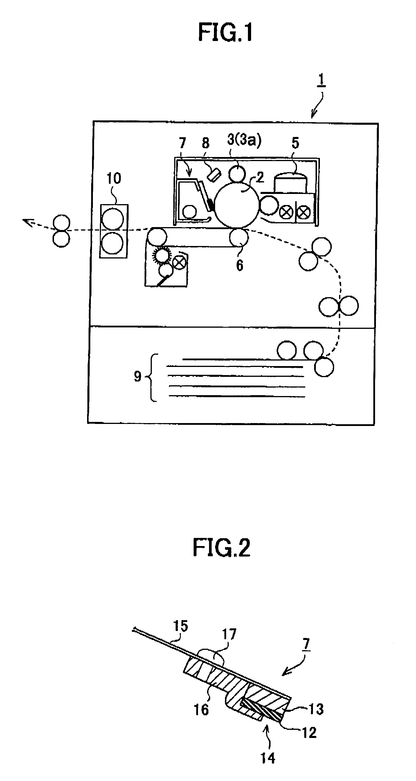
[0052]FIG. 1 is a schematic drawing showing an entire structure of an image forming apparatus provided with a cleaning apparatus according to the present invention.

[0053]In an image forming apparatus 1 shown in FIG. 1, a charging apparatus 3 (charging roller 3a) which uniformly charges a surface of an image carrier drum (image carrier) 2, an exposing apparatus (not shown) which forms a latent image on the uniformly charged surface of the image carrier drum 2, a developing apparatus 5 which forms a toner image by applying a toner (charged developer) to the latent image on the surface of the image carrier drum 2, a transferring apparatus 6 which transfers the toner image to a recording sheet (not shown) by using, for example, a transfer belt, a transfer roller, or a charger, a cleaning apparatus 7 which removes toner remaining on the image carrier drum 2 after the transfer of the toner image, and a charge removing apparatus 8 which removes electric potential remaining on the image car...

second embodiment

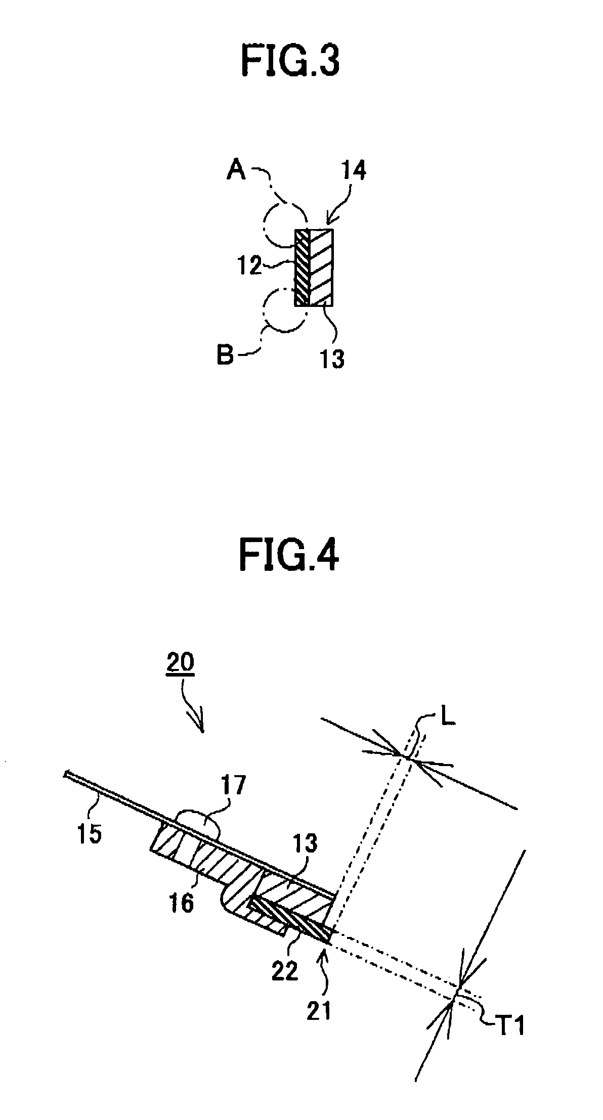
[0066]In a cleaning apparatus according to the present invention, cleaning performance is further improved by setting the projection of the blade member 22 from the supporting plate 15 of a blade chip 21 to the outside in a width direction (distance from the distal end of the supporting plate 15 of a blade chip 21 to the distal end of the blade member 22) to a prescribed degree (See FIG. 4).

[0067]That is, in cleaning the image carrier drum 2, the blade member 22, serving as a cleaning member, is required to have a function of blocking the toner remaining on the image carrier drum 2. The blockage, which is created by abutting a tip portion of the blade member 22 against the image carrier drum 2, is determined by the degree of hardness (e.g. degree of hardness of rubber) of the blade member 22 and the force of the tip portion of the blade member 22 abutting against the image carrier drum 2. Therefore, in a case where the blade member 22 does not project beyond the distal end of the re...

third embodiment

[0075]With the cleaning apparatus 25 according to the present invention, the frictional force generated between the blade member 22 and the image carrier drum 2 can be reduced by applying vibration to the blade chip 21 (blade member 22). Accordingly, the wear of the blade member 22 as well as that of the image carrier drum 2 can be reduced, to thereby expand its longevity. Furthermore, since frictional force is reduced in such manner, the curling of the blade (member) can be prevented. Therefore, the blade edge (distal end shape of the blade member 22) can be prevented from being deformed. Accordingly, the blade member 22 is able to steadily provide a satisfactory cleaning performance. Furthermore, the image carrier drum 2 can be rotatively driven steadily since the frictional load applied to the image carrier drum 2 is reduced. Accordingly, image forming operations that are associated with the rotation of the image carrier drum 2 can also be performed steadily. As a result, image q...


PUM


Abstract

A cleaning apparatus is disclosed that includes a blade chip having a rubber plate member and a reinforcing plate member that are joined together, a supporting plate supporting the blade chip, and a holder pressing the blade chip against the supporting plate.

Description

BACKGROUND OF THE INVENTION[0001]1. Field of the Invention[0002]This invention relates to an image forming apparatus using an electrophotographic method or an electrostatic recording method, for example, a copier, a printer, or a facsimile, and more particularly, to an image forming apparatus having a cleaning apparatus.[0003]2. Description of the Related Art[0004]Along with growth of the information society, there is a growing demand for an image forming apparatus (e.g. electrophotographic copier, electrophotographic printer) which forms images with higher speed, which requires less space, which generates high quality images, and which has an extensive longevity. Along with this growing demand, there is a demand for an electrophotographic image carrier used for an image forming apparatus which responds at high speed, which has a small size, and which provides high endurance. Accordingly, an image carrier applied with amorphous-Si, or an organic image carrier having an organic coat ...

Claims


Application Information

Patent Timeline
Patent Type & Authority Patents(United States)
IPC IPC(8): G03G21/00
CPCG03G21/0029G03G21/0017
Inventor NARUSE, OSAMUNAKANO, TOHRUHORIKE, MASANORI
Owner RICOH KK
Why Eureka
Try Eureka