Door handle apparatus

a technology for door handles and handle handles, which is applied in the field of door handle apparatuses, can solve the problems of limited versatility of the apparatus db>1/b>, limited design of the handle grip h, and reduced versatility of the apparatus, so as to reduce costs, enhance mounting strength and simplify the process of mounting and dismounting the detection sensor

Inactive Publication Date: 2006-06-20
HONDA MOTOR CO LTD
View PDF20 Cites 61 Cited by
  • Summary
  • Abstract
  • Description
  • Claims
  • Application Information

AI Technical Summary

Benefits of technology

[0010]Then, the invention is made with a view to solving the problems, and an object thereof is to provide a door handle apparatus which can make it difficult for the design properties thereof to be damaged, which can simplify the construction which allows for a selection of fitment of the smart entry system to thereby attempt to reduce costs, and which can simplify the mounting and dismounting of a detection sensor and facilitate the replacement of parts, so that the repair and replacement costs can be reduced which are incurred when the detection sensor fails.

Problems solved by technology

JP-A-2002-295094 (paragraphs 0015 to 0018, FIG. 2) In the door handle apparatus D1 shown in FIG. 8A, however, since the detection sensor K (refer to FIG. 9A) is constructed to be installed in the handle grip H, there is caused a problem that the size of the detection sensor K is limited, and since a construction is needed to enable the installation of the sensor, there is caused another problem that the design of the handle grip H is limited.
In addition, there is caused a further problem that the apparatus D1 is inferior in versatility (application to other types of automobiles).
Due to this, the construction around the handle needs to be designed so as to allow for a change in specification depending on whether or not the sensor is equipped, and as a result, there is caused a problem that the related cost needs to be increased.
In addition, in the door handle apparatus D1 shown in FIG. 9A, since the detection sensor K is constructed to be integrally installed in the handle grip H, when the detection sensor K fails, there may occur a case where the replacement of parts should be dealt with by replacing the whole door handle apparatus D1, there is caused a problem that the repair cost is increased.

Method used


Image

  • Door handle apparatus
  • Door handle apparatus
  • Door handle apparatus

Examples


first embodiment

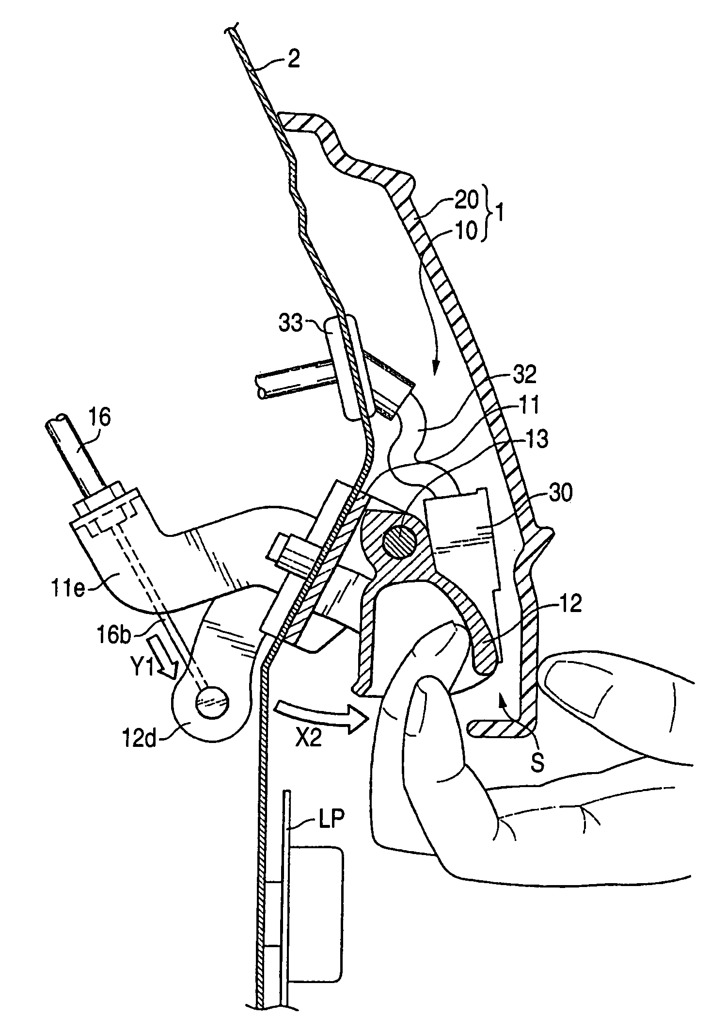
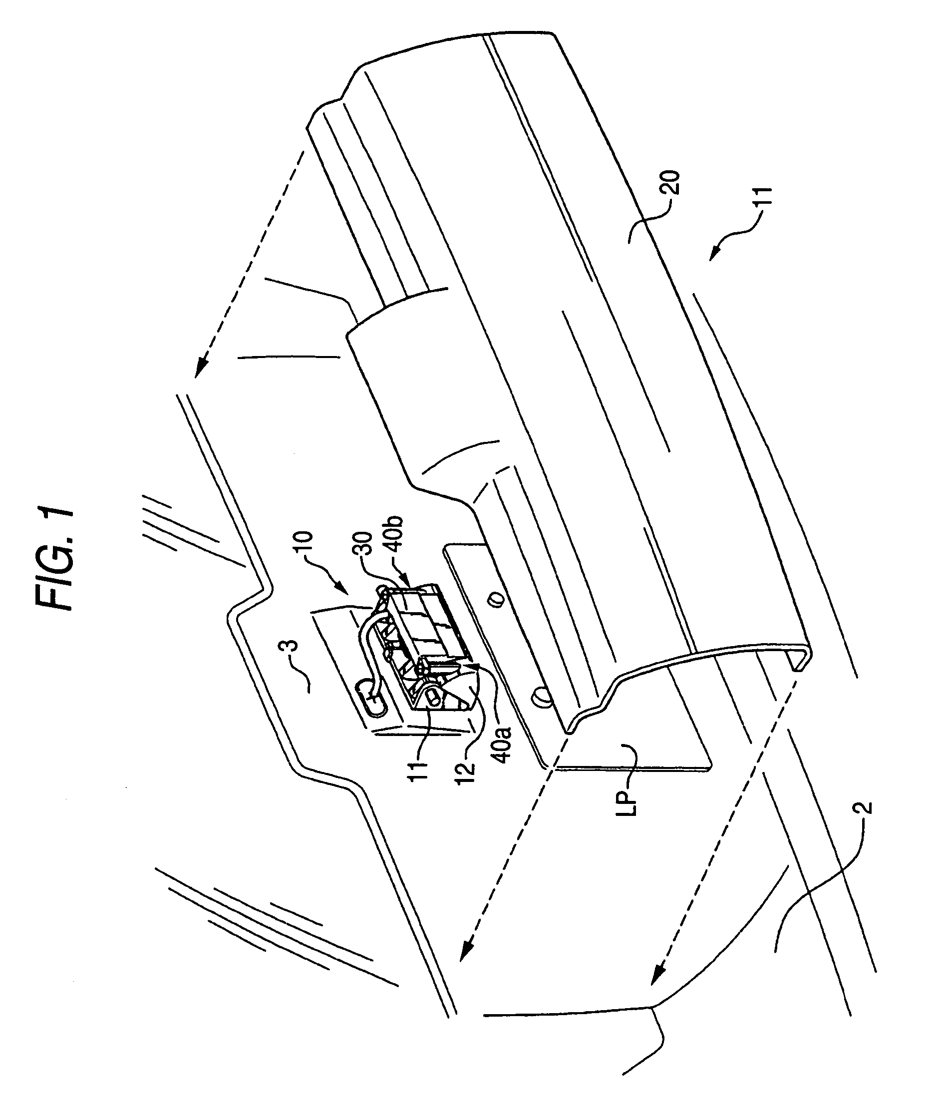
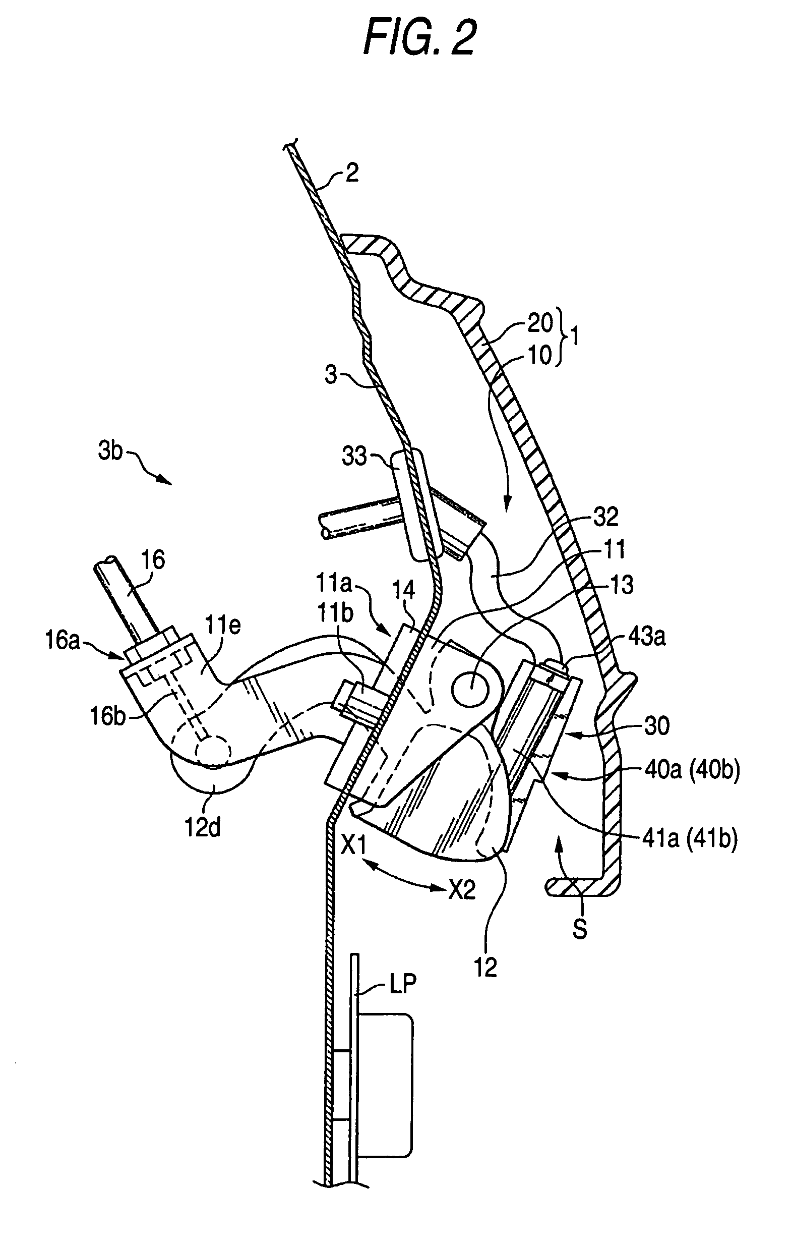
[0045]In the drawings to be referred to, FIG. 1 is a perspective view of a rear part of a vehicle body showing a door handle apparatus according to a first embodiment, FIG. 2 is a vertical cross-sectional view of a main part of the rear part of the vehicle body which is situated around the door handle apparatus of the first embodiment, FIG. 3 shows a door handle assembly, FIG. 3A being an enlarged back-side view of the assembly, FIG. 3B being a cross-sectional view taken along the line b—b in FIG. 3A, and FIG. 4 shows perspective views of the door handle assembly, FIG. 4A being a partly exploded perspective view of the assembly, FIG. 4B being a perspective view showing a state where the assembly is mounted on a back door.

[0046]As shown in FIGS. 1, 2, a door handle apparatus 1 includes a door handle assembly 10 having a door handle 12 and a cover member 20. Then, a detection sensor 30, which can be used as a sensor for a smart entry system and detect the approach of an operator towar...

second embodiment

[0071]FIG. 6 is a vertical cross-sectional view of a main part of a rear part of the vehicle body around a door handle apparatus according to a second embodiment of the invention, FIGS. 7A, 7B are perspective views of a cover member and a detection sensor of the door handle apparatus according to the second embodiment, wherein FIG. 7A is an exploded perspective view illustrating a state before the detection sensor is mounted on the cover member and FIG. 7B is a perspective view illustrating a state after the mounting is completed. In the drawings that are referred to, the second embodiment is identical with the first embodiment in that a detection sensor 30 is provided between a door handle 12 and a cover member 20 but is different in that the detection sensor 30 is mounted on the cover member 20 side (a front surface 20a of the cover member 20).

[0072]As shown in FIGS. 6, 7A, 7B, a door handle apparatus 5 according to the embodiment has a fixing portion 50 and a support portion 60 w...


PUM


Abstract

A door handle apparatus having a door handle 12 which is provided on a back door of an automobile in such a manner as to oscillate freely and a cover member 20 for covering the door handle 12, wherein a detection sensor 30 for detecting the approach of an operator toward the door handle 12 is provided between the door handle 12 and the cover member 20.

Description

BACKGROUND OF THE INVENTION[0001]The present invention relates to a door handle apparatus, and more particularly to a door handle which is preferably used for a smart entry system equipped on an automobile.[0002]Conventionally, there has been known an automobile which is equipped with, as an automotive security system, a so-called smart entry system in which a recognition code is exchanged between a transmitter-receiver carried by an operator (for example, the driver) and a transmitter-receiver provided on the automobile side, whereby a lock of a door of the automobile is automatically opened when the operator only approaches the door of the automobile, whereas the lock of the door is automatically closed when the operator only leaves from the door.[0003]In this system, proximity sensors are provided on automotive door handle apparatuses D1 to D3 shown in FIGS. 8A to 8C as a trigger unit for executing a recognition process.[0004]For example, in the door handle apparatus D1 using a h...

Claims


Application Information

Patent Timeline
Patent Type & Authority Patents(United States)
IPC IPC(8): E05B49/00E05B1/00E05B81/78E05B85/18
CPCB60R25/246E05B85/18E05B81/78E05B81/77Y10T70/7068Y10T292/57
Inventor SAITOH, HAJIMEYAMADA, KAZUHIKOICHINOSE, TOMOFUMI
Owner HONDA MOTOR CO LTD
Why Eureka
Try Eureka