Perforated fin heat exchangers and catalytic support

a technology of heat exchangers and fins, which is applied in indirect heat exchangers, laminated elements, lighting and heating apparatus, etc., can solve the problems of difficult to bond firmly to tubes, and achieve the effect of high heat exchange rates

Inactive Publication Date: 2006-06-20
POWERTAP HYDROGEN FUELING CORP
View PDF67 Cites 27 Cited by
  • Summary
  • Abstract
  • Description
  • Claims
  • Application Information

AI Technical Summary

Benefits of technology

[0004]In searching for an alternative to currently known heat exchangers, we have found that perforated metal sheets can be advantageously used in a fin-tube type heat exchanger. A tube, or a plurality of tubes, carrying a plurality of fins made of perforated material, allows high rates of heat exchange (proportional to the thermal conductivity of the heat exchange materials) between a first fluid flowing alon

Problems solved by technology

However, they are expensive, and can

Method used


Image

  • Perforated fin heat exchangers and catalytic support
  • Perforated fin heat exchangers and catalytic support
  • Perforated fin heat exchangers and catalytic support

Examples


examples

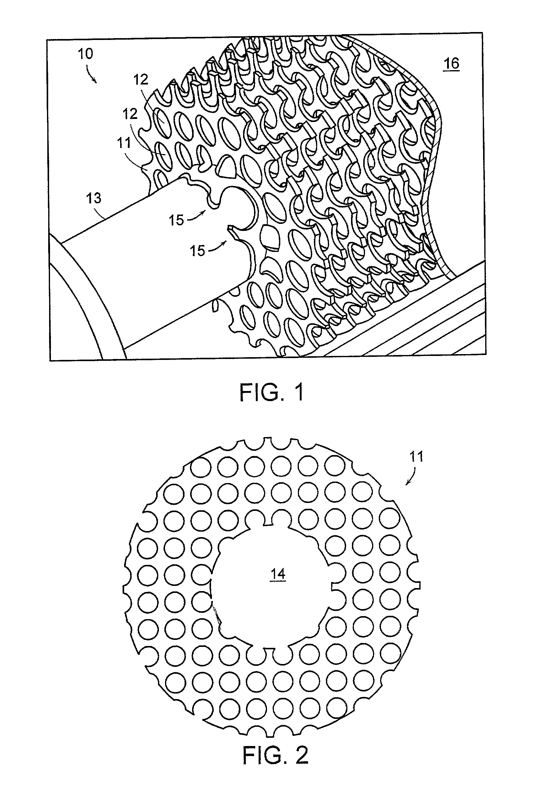
[0026]FIG. 1 shows an example of a heat exchanger 10 according to the principles of the invention. In this embodiment, circular discs 11 (1.5 inches in diameter) with a central hole (0.5 inch diameter) were punched from a 20 g gauge sheet of copper having regular perforations 12. A central flange 15 was formed in the disks by flaring the central hole to obtain a final diameter of 0.75 inch, thereby forming a flange surrounding the hole of about 0.125 inch in height. The punched disk was used as a perforated fin. The fins were slid onto a 0.75 inch diameter tube 13 of 316 stainless. The flanges provided a predetermined spacing of the discs on the tube. This simple press fit provided adequate heat exchange. The fin-tube assembly can also be permanently bonded together, by brazing, for instance, to improve stability and heat exchange. This can be done by coating the tubing with copper brazing material before pressing on the tubes. The assembly can then be brazed in a hot oven and allow...


PUM

PropertyMeasurementUnit
Temperatureaaaaaaaaaa
Flow rateaaaaaaaaaa
Shapeaaaaaaaaaa

Abstract

Perforated fins are provided to improve the capabilities of fin and tube type heat exchangers, and to adapt them for flow outside of the tube that is essentially parallel to the axis of the tube. The fins are made of a thermally conductive material, such as metal, with perforations in the fins. Fins can be of any shape. Typically, one or more tubes or binding posts pass through the fins. The fins are attached to the tube or post by press fitting, furnace or torch brazing, welding, or other method of mechanical bonding. The perforations allow heat exchange with the contents of a tube of a fluid flowing essentially parallel to the axis of the tube, in contrast to conventional fin-tube heat exchangers. The fins may also be bonded to a post or other securing means and inserted into the inside of a tube or other hollow body to improve efficiency of heat exchange. In addition, the fins may carry a catalyst, optionally carried on a washcoat or similar treatment to increase surface area.

Description

RELATED APPLICATION[0001]This application claims the benefit of U.S. Provisional Application No. 60 / 304,987, filed Jul. 12, 2001, the entire teachings of which are incorporated herein by reference.BACKGROUND OF THE INVENTION[0002]A variety of heat exchanger types are known. A common form, particularly for air or gas heat exchange with another gas or a liquid, is a fin-tube type exchanger. These are familiar in domestic heating and radiators, for example. In this type, one fluid flows through a tube, and the other fluid, typically a gas, flows essentially perpendicularly to the tube. Fins are attached to the tube to increase the area available for heat exchange, thereby minimizing the length of pipe and the associated pressure drop.[0003]In seeking to further increase the rate of heat exchange from a tube, porous metal foams have been used as replacements for fins. These have the advantage of allowing flow of the outer fluid along the tube length, either counter-current or co-current...

Claims


Application Information

Patent Timeline
IPC IPC(8): F28F1/30F28F1/24F28F1/32
CPCF28F1/325F28F1/24
Inventor NORTHROP, WILLIAM F.
Owner POWERTAP HYDROGEN FUELING CORP
Why Eureka
Try Eureka