Bottom tensioned offshore oil well production riser

a technology of oil wells and risers, which is applied in the direction of drilling pipes, drilling/well accessories, sealing/packing, etc., can solve the problems of increasing the cost of the tensioning system, prohibitively expensive to deploy, and insufficient stability, so as to achieve simple fabrication and deployment and reliable operation.

Active Publication Date: 2006-06-20
DEEPWATER TECH
View PDF23 Cites 13 Cited by
  • Summary
  • Abstract
  • Description
  • Claims
  • Application Information

AI Technical Summary

Benefits of technology

[0016]In accordance with the present invention, an offshore oil well riser system is provided that efficiently compensates for the motions of an associated floating drilling or production platform. The riser system is relatively inexpensive, simple to fabricate and deploy, and reliable in operation.
[0018]This riser system is primarily applicable to low heave floating platforms, such as SPARs, TLPs, Deep Draft semi submersibles, and to other platforms used in relatively calm waters, e.g., west of Africa and Brazil. The novel riser system can be used in either dry tree or wet tree completion systems, and the use of a low heave floater minimizes the maximum “stroke,” or vertical movement, required of the bottom end connection and tensioning assembly.
[0019]The conduit can comprise a single riser pipe, or a bundle thereof, each connected to a respective well through an associated jumper. The bundle of riser pipes may comprise a large, outer casing in which a plurality individual tubular risers are arranged. The annular space of the large casing can be used for facilitating the flow of petroleum through the riser system, e.g., to insulate the individual risers against cold sub-sea ambient temperatures, or alternatively, to heat the risers actively, such as by the injection of steam or hot water into the annular space. The outer casing can also provide a “double-hull” redundancy in case of a breach in one of the risers.
[0021]One advantageous feature of the present invention is that, while the conduit is free to move vertically to accommodate the vertical motions of the floating support platform, horizontal movement of the bottom end of the conduit is substantially constrained. This eliminates the type of movement of the bottom end of the riser that leads to high fatigue stresses in the associated jumpers. Another feature of the invention is that the bottom end of the conduit is pivotally connected to the constraining assembly e.g., with a universal joint, a pinned joint, a stress joint, or the like, which enables the riser system to pivot freely relative to its bottom end and thereby accommodate horizontal motions of the floating support while eliminating harmful bending stresses in the conduit.

Problems solved by technology

However, as tension and stroke requirements of the active tensioners increases, they become prohibitively expensive to deploy.
Manufacturing and deploying individual buoyancy cans for each riser is also costly.
This requirement dramatically increases the cost of the tensioning system, and in some deepwater applications, where the weight of the riser is substantially greater, can result in an overstress of the risers.
This type of riser system is both expensive and difficult to deploy.
The relatively larger motions experienced by these types of platforms make the support of vertical drilling and production risers impractical.
However they are both heavy and expensive.
However, due to their greater stiffness, they are prone to fatigue problem resulting from the dynamic motions that they must undergo, and may require relatively greater lengths to accommodate the motions of the platform satisfactorily.
Thus, in the former types of systems, the platform motions are absorbed by the upper part of the riser, and therefore require a critical degree of top tension to prevent a destructive compression of the risers and the occurrence of riser collisions, and in the latter types of the systems, the risers must sag to absorb motions, and therefore require substantially great lengths of pipe to function.
In light of the foregoing drawbacks of the prior art riser systems, a long felt but as yet unsatisfied need exists in the petroleum industry for a simple, low-cost, yet safe and reliable off-shore oil well riser system that compensates for the motions of an associated floating platform.

Method used


Image

  • Bottom tensioned offshore oil well production riser
  • Bottom tensioned offshore oil well production riser
  • Bottom tensioned offshore oil well production riser

Examples


Embodiment Construction

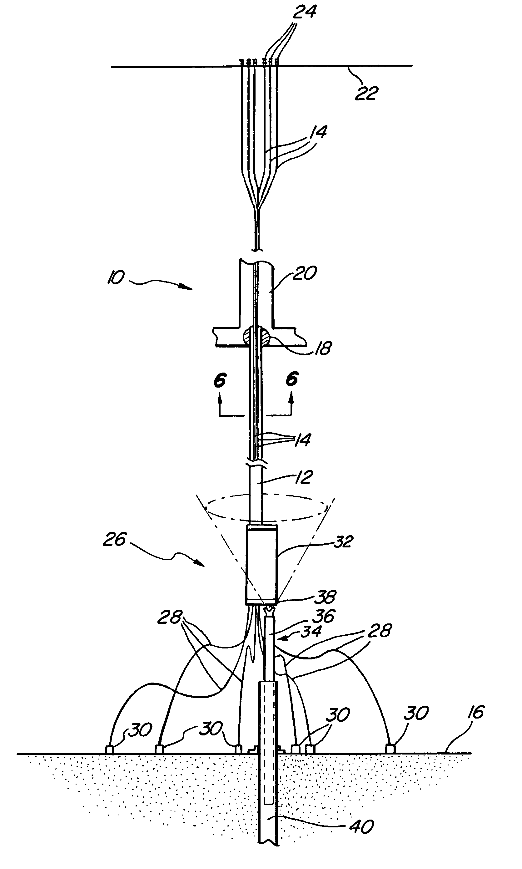
[0035]A first exemplary embodiment of a bottom tensioned offshore oil well riser system 10 in accordance with the present invention is illustrated in the elevation view of FIG. 5. The exemplary riser system illustrated comprises a tubular casing or conduit 12 enclosing a plurality of individual tubular riser pipes 14 suspended from a floating platform (omitted for clarity) and extending downward substantially vertically toward the sea floor 16 through a flexible joint 18 located at the keel 20 of the floating platform. Each of the individual riser pipes 14 extends upward to a well or production deck 22 of the platform, and is terminated thereat by an individual tree 24.

[0036]A bottom end connection and tensioning assembly 26 is attached to the bottom end of the conduit 12 at a distance of about 50 to 150 feet above the sea floor. The connection and tensioning assembly comprises jumpers 28 that connect the bottom end of each riser pipe to a respective sub-sea well equipment 30, a wei...


PUM


Abstract

An offshore oil well riser system comprises one or more tubular conduits suspended from a floating platform and having bottom ends extending downward substantially vertically toward the sea floor. A bottom end connection and tensioning assembly is disposed at the bottom ends of the conduits and comprises a jumper for connecting the bottom end of each conduit to an associated sub-sea oil well, a weight for applying a vertical tension in the conduits, and an apparatus for constraining the bottom end of the conduits against horizontal movement, while enabling them to move freely in a vertical direction and to pivot freely at their bottom ends in response to motions of the platform on the water surface. The riser system is useful with a wide variety of floating platforms, and can be employed in either dry tree or wet tree completion systems.

Description

CROSS-REFERENCE TO RELATED APPLICATIONS[0001]This Application claims benefit of U.S. Provisional Patent Application Ser. No. 60 / 478,880, filed Jun. 16, 2003.STATEMENT REGARDING FEDERALLY SPONSORED RESEARCH OR DEVELOPMENT[0002](Not Applicable)REFERENCE TO APPENDIX[0003](Not Applicable)BACKGROUND OF THE INVENTION[0004]1. Field of the Invention[0005]This invention relates, in general, to offshore oil well risers that convey petroleum from producing wells on the sea floor to a floating platform on the sea surface, and in particular, to risers that are tensioned at their bottom ends to enable them to accommodate large motions of the platform relative to the wells without sustaining damage.[0006]2. Description of Related Art[0007]Conventional “dry tree” offshore floating petroleum production platforms include such “low heave” platforms as Spars, Tension Leg Platforms (“TLPs”), and Deep Draft semi submersible platforms. These platforms are capable of supporting a plurality of vertical prod...

Claims


Application Information

Patent Timeline
Patent Type & Authority Patents(United States)
IPC IPC(8): E21B29/12E21B7/12E21B19/00
CPCE21B19/006E21B19/002
Inventor HORTON, III, EDWARD E.
Owner DEEPWATER TECH
Why Eureka
Try Eureka