

Drive system seal
a technology of drive system and seal, which is applied in the field of infusion pump improvement, can solve the problems of increasing the overall size of the pump, and increasing the cost of disposable items,
- Summary
- Abstract
- Description
- Claims
- Application Information
AI Technical Summary
Benefits of technology
Problems solved by technology
Method used
Image

Examples
Embodiment Construction
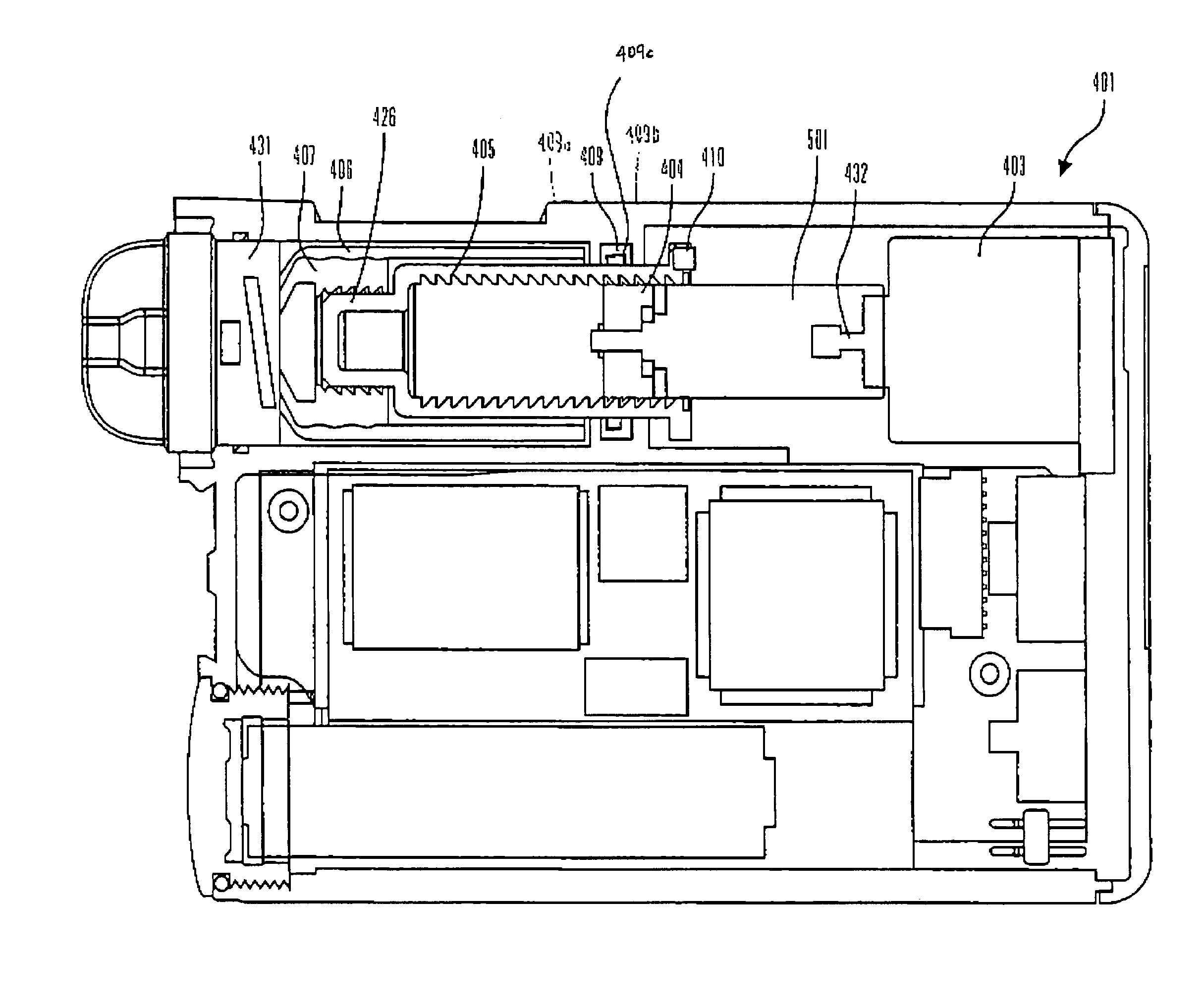
[0022]Embodiments of the present invention provide an improved apparatus for dispensing a medication fluid from a reservoir adapted to contain the fluid. In accordance with an embodiment of the present invention, the apparatus includes a reservoir cavity adapted to receive the reservoir, a drive system, and at least one plunger slider. One end of the at least one plunger slider is coupled to the drive system, and the other end of the at least one plunger slider is releasably coupled to the reservoir. Also, the at least one plunger slider is adapted to translate from a retracted position to an extended position to dispense the fluid from the reservoir in response to actuation by the drive system. The apparatus further includes a sealing ring mounted around the at least one plunger slider, and a spring disposed within the sealing ring. The sealing ring with the spring disposed therein is adapted to allow the at least one plunger slider to translate from the retracted position to the e...
PUM
 Abstract
Description
Claims
Application Information