Method and apparatus for detecting particles in a gas flow

a gas flow and particle detection technology, applied in the direction of instruments, sampling, suspensions and porous materials, etc., can solve the problems of limited sensitivity to light particles, non linearity, and tendency to have display velocity dependence, so as to remove the velocity dependence of detection

Inactive Publication Date: 2006-06-20
GOYEN CONTROLS CO PTY LTD
View PDF15 Cites 11 Cited by
  • Summary
  • Abstract
  • Description
  • Claims
  • Application Information

AI Technical Summary

Benefits of technology

[0033]According to another aspect of the present invention there is provided a method of improving the linearity of the signal produced by a triboelectric particle detector including the steps of:

Problems solved by technology

As will be appreciated by a person skilled in the art, known particulate emission monitors have various drawbacks, such as, limited sensitivity to light particles, a tendency to have display velocity dependence in their measurements, non linearity between particle concentration and detector signal and limited diagnostic capabilities, to name but a few.

Method used


Image

  • Method and apparatus for detecting particles in a gas flow
  • Method and apparatus for detecting particles in a gas flow
  • Method and apparatus for detecting particles in a gas flow

Examples


Embodiment Construction

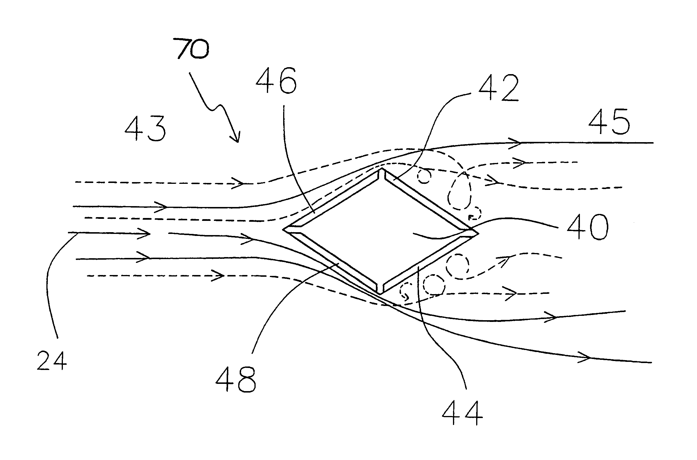
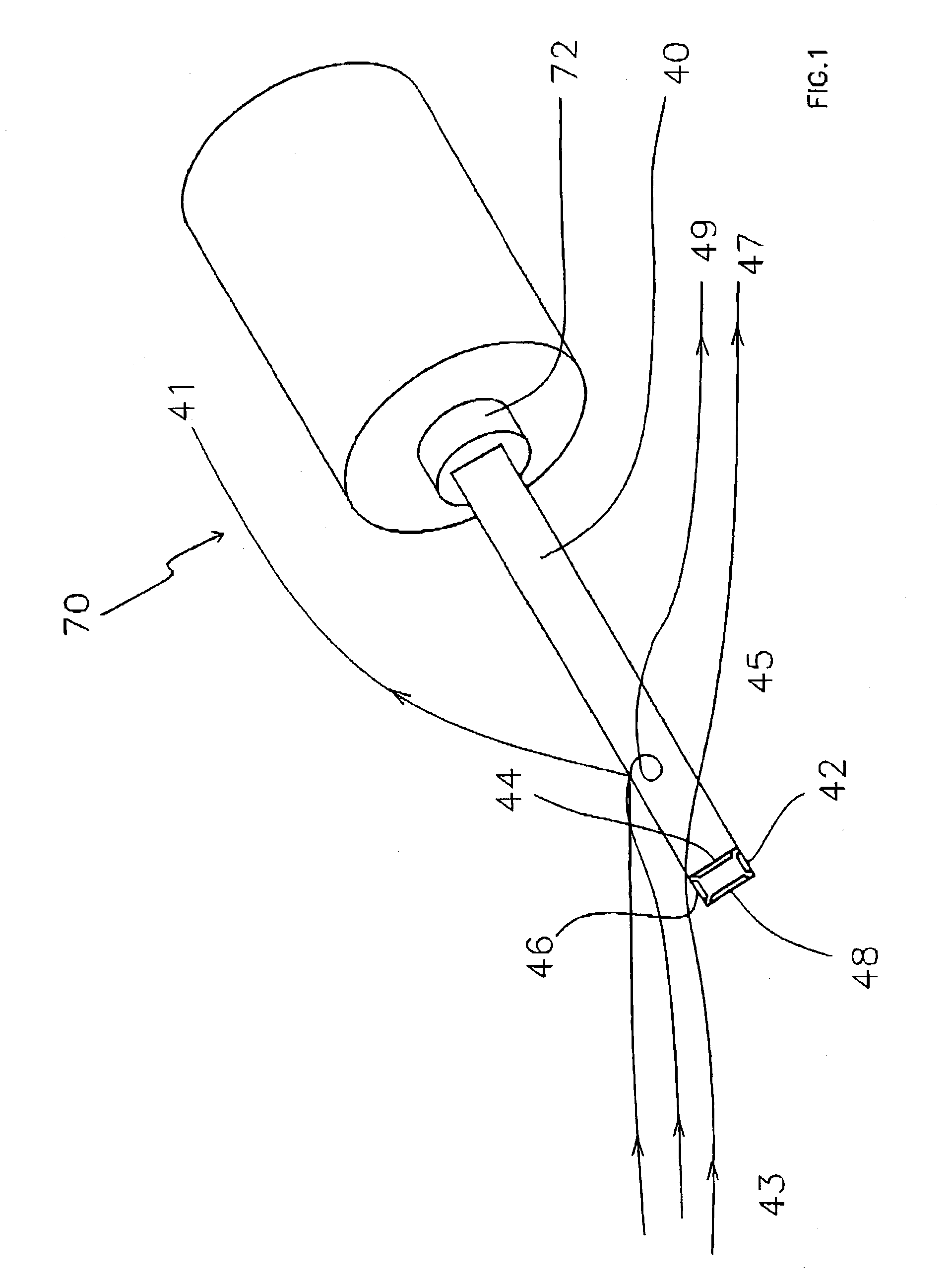
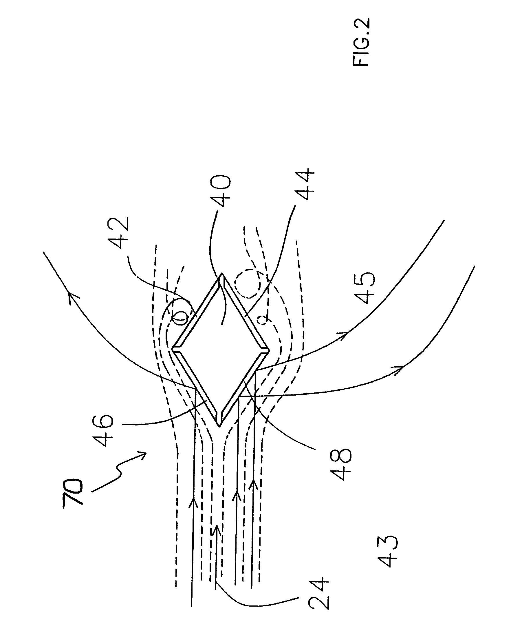
[0113]FIG. 1 illustrates a detection means being an embodiment of the present invention. The detection means 70 is adapted to detect particulate material entrained in a gas flow, the direction of which is indicated by the arrow shown in the streamlines 41, 47, 49. The detection means 70 includes a probe shaft 40 with a generally square cross-section having four faces. On each of the faces of the probe shaft 40 there is a separate and electrically isolated probe electrode 42, 44, 46, 48. Probe electrodes 46 and 48 are located on the upstream side 43 of the probe shaft 40 and probe electrodes 42 and 44 are located on the downstream side 45 of the probe shaft 40. Detection means 70 also includes an insulating sleeve 72 to prevent current leakage from the probe electrodes 42, 44, 46, 48 to a duct (not shown).

[0114]When the detection means 70 is placed in a gas flow, particulate material which is suspended in the gas flow interacts with the probe electrodes 42, 44, 46, 48 to produce a si...


PUM

PropertyMeasurementUnit
frequencyaaaaaaaaaa
frequencyaaaaaaaaaa
frequencyaaaaaaaaaa

Abstract

The application discloses several methods of detecting particles moving in a gas flow, a detection means (70), a method of improving the linearity of the signal produced by a triboelectric particle detector, a method to test a signal path of an emission monitor, an emission monitor for detecting particles, and a method of detecting faults in a triboelectric probe of system for detecting particles entrained in a gas flow. The particle detection means (70) includes a gas flow deflection means (40) having an upstream face (43) and a downstream face (45) and a detector (42, 44) associated exclusively with the downstream face (45). Deflecting the gas flow creates vortices that have little effect on the large particles, but cause the small particles to move close to the detectors on the downstream face. Therefore the downstream detectors (42, 44) are particularly sensitive to light particles. The method improves of small particles and provides accurate particle counts.

Description

[0001]This Application is a continuation of International Application PCT / AU01 / 00417 filed 11 Apr. 2000 and Applicant specifically claims priority from said International Application.FIELD OF THE INVENTION[0002]The invention relates to a method and apparatus for detecting particles entrained in a gas flow and to an apparatus capable of carrying out such a method. More particularly, the invention relates to a triboelectric emission monitor and an optical dynamic emission monitor.BACKGROUND OF THE INVENTION[0003]There are several known means of measuring the level of particulate material entrained in a gas flow. These can be split into a number of categories including those based on electrostatic or triboelectric phenomena on the one hand, and those based on optical phenomena on the other.[0004]As will be appreciated by a person skilled in the art, known particulate emission monitors have various drawbacks, such as, limited sensitivity to light particles, a tendency to have display ve...

Claims


Application Information

Patent Timeline
Patent Type & Authority Patents(United States)
IPC IPC(8): G01N37/00G01N15/06G01N27/60
CPCG01N27/60G01N15/0656
Inventor ROE, MORRIS ANTHONY
Owner GOYEN CONTROLS CO PTY LTD
Why Eureka
Try Eureka