Electric heater

a technology for electric heaters and heaters, applied in the field of electric heaters, can solve the problems of inability to provide an initial heating effect, damage or separation of conventional electric heaters, electric accidents and fires, etc., and achieve the effects of improving assembly performance and productivity, increasing heating value and thermal conductivity, and increasing contact efficiency among components

Active Publication Date: 2006-06-20
JAHWA ELECTRONICS +1
View PDF11 Cites 44 Cited by
  • Summary
  • Abstract
  • Description
  • Claims
  • Application Information

AI Technical Summary

Benefits of technology

[0033]Accordingly, the present device has been made in view of the above problems occurring in the prior art, and it is an object of the present invention to provide an electric heater, which electrically and mechanically protects heating means from the outside, which increases heating value and thermal conductivity by increasing contact efficiency among components, and which improves assembly performance and productivity.

Problems solved by technology

Finally, the heating system has a problem in that it cannot provide an initial heating effect after the engine is driven because it takes long time to increase heat of the engine more than a predetermined temperature.
First, there may occur electric accidents and fires due to electric short if a great deal of conductive liquid and metal are induced from the outside because the metal band pieces 504a are not electrically insulated from the adjacent radiation fin 503.
Second, the conventional electric heater may be damaged or separated due to severe vibration of the car since the heating bodies 504 are exposed to the outside in a state where it is simply interposed between the radiation fins.
Third, the upper and lower frames 501 and 502 are fixed only by the side frame 507 in a state where they compress the wave type spring 506 and the radiation fins 503.
However, the internal web 505 must be mounted to prevent buckling of the radiation fins 503 generated when excessive power is transferred to a certain position of the radiation fins 503 by the shape of the wave type spring 506, and so, the number of the components of the electric heater is increased and the assembly efficiency and productivity are deteriorated.

Method used


Image

  • Electric heater
  • Electric heater
  • Electric heater

Examples


first embodiment

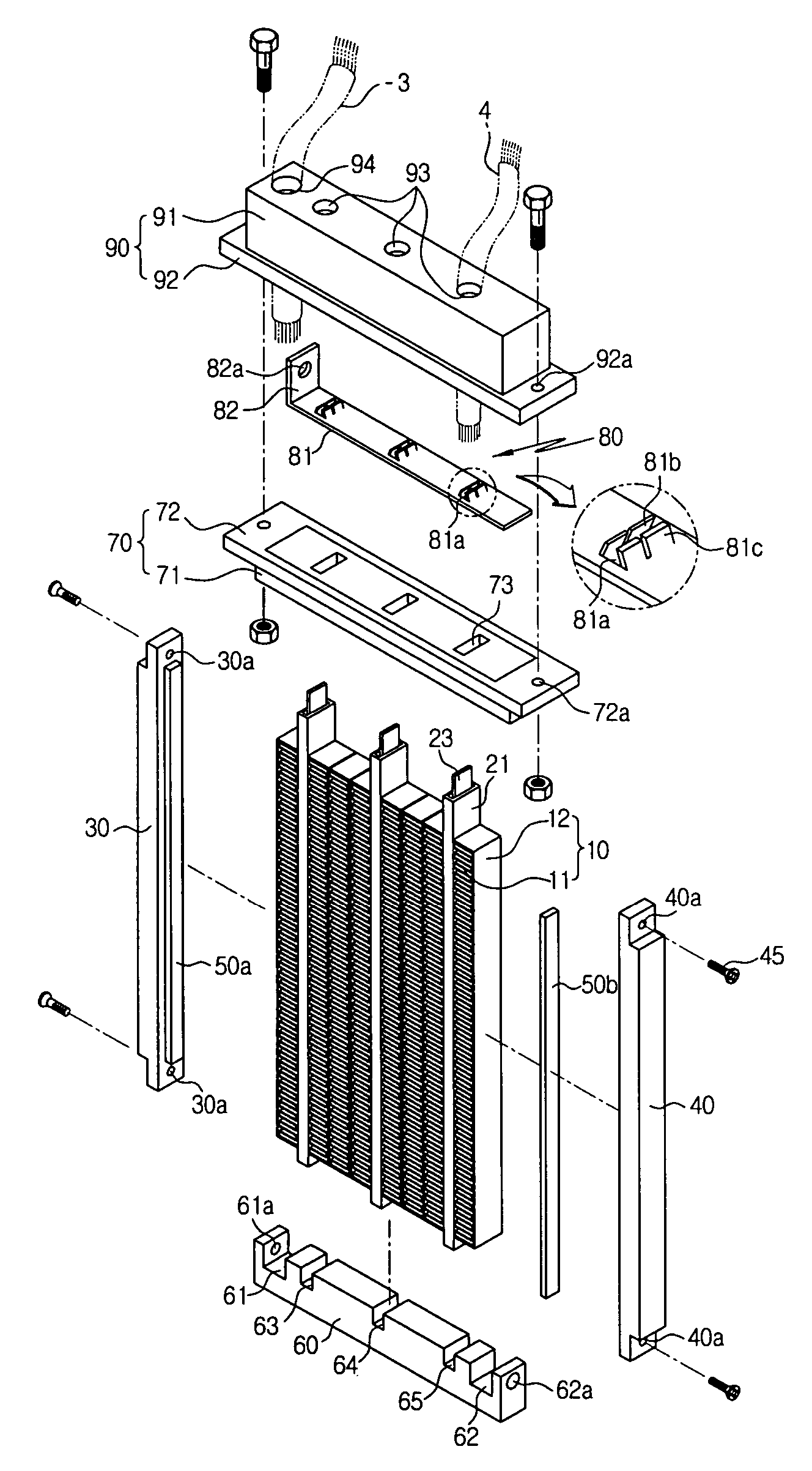
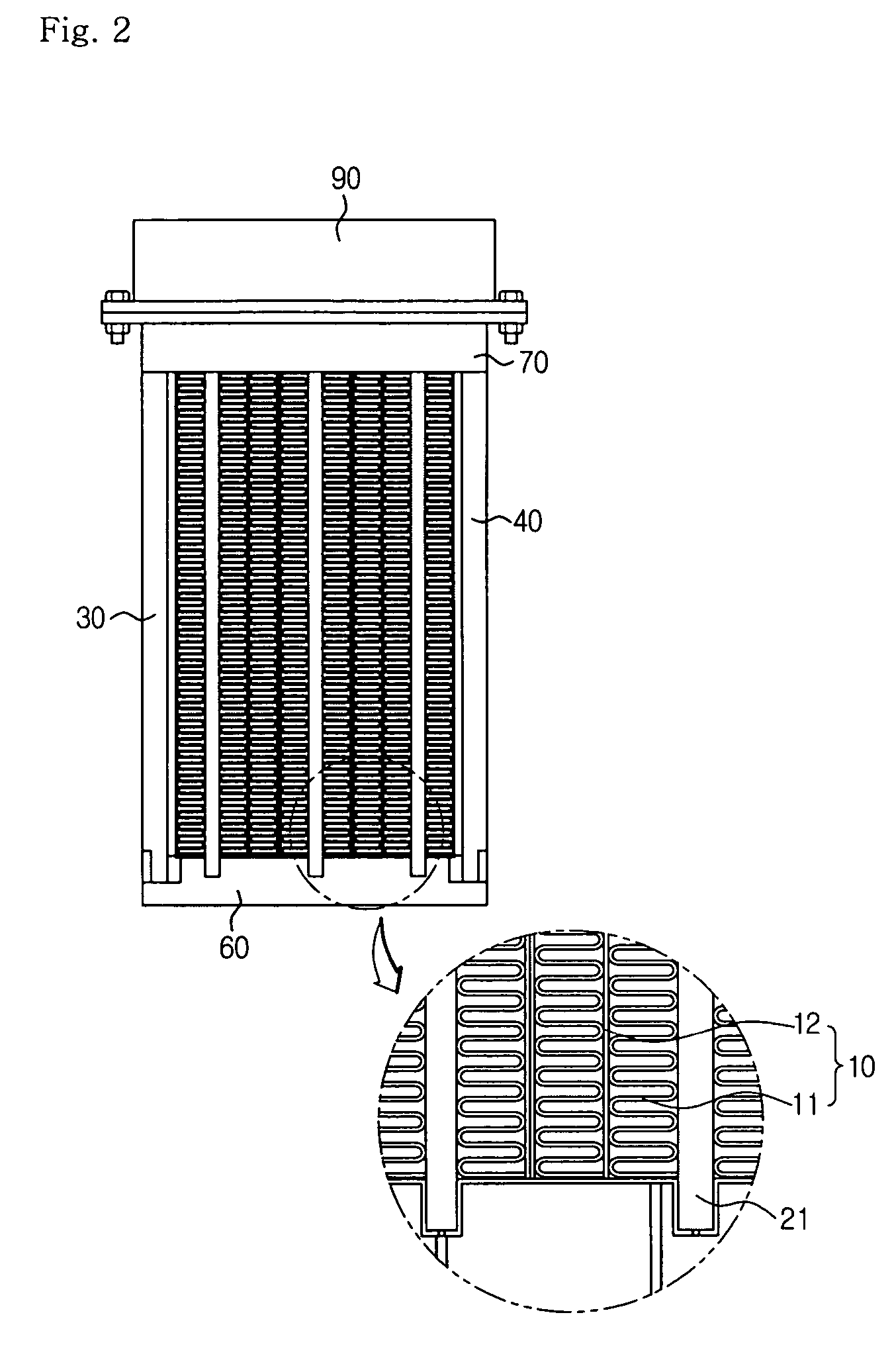
[0063]FIG. 2 is a front view of an electric heater according to a first preferred embodiment of the present invention, FIG. 3 is an exploded perspective view of the electric heater according to the first preferred embodiment, FIG. 4 is an exploded perspective view of heating means installed on the electric heater according to the first preferred embodiment, and FIG. 5 is a sectional view showing a state where the heating means of FIG. 4 is assembled inside a flat tube.

[0064]The electric heater according to the first preferred embodiment of the present invention includes a plurality of radiation members 10, heating means 20, a plurality of flat tubes 21, a first support frame 30, a second support frame 40, a first cap 60, and a second cap 70.

[0065]The radiation member 10 includes a radiation fin 11 and a radiation fin supporting plate 12 surrounding the radiation fin 11 and formed integrally with the radiation fin 11 by brazing.

[0066]The radiation fin 11 is in a corrugated type and m...

second embodiment

[0134]FIG. 6 is a front view of an electric heater according to a second preferred embodiment of the present invention, FIG. 7 is an exploded perspective view of the electric heater according to the second preferred embodiment, FIG. 8 is an exploded perspective view of heating means installed on the electric heater of the second preferred embodiment together with a first preferred embodiment of a first wiring part, FIG. 9 is a perspective view of the first preferred embodiment of the first wiring part, which is an enlarged perspective view taken along the line of ‘A’ of FIG. 8, FIG. 10 is an enlarged perspective view taken along the line of ‘B’ of FIG. 8, FIG. 11 is a sectional view showing an assembled state of the lower end part of the electric heater according to the second preferred embodiment, FIG. 12 is an exploded perspective view showing an assembled state of the upper end part of the electric heater according to the second preferred embodiment, FIG. 13 is a perspective view...


PUM


Abstract

The present invention relates to an electric heater, which electrically and mechanically protects heating means from the outside, increases heating value and thermal conductivity by increasing contact efficiency among components, and improves assembly efficiency and productivity. The electric heater includes: a plurality of radiation members, each having a radiation fin and a radiation fin supporting plate surrounding the radiation fin and formed integrally with the radiation fin by brazing; a plurality of flat tubes arranged between the radiation members and having heating means therein for generating heat when electric power is supplied; first and second support frames oppositely arranged at sides of the outermost radiation members for supporting and fixing the radiation members and the flat tubes; and first and second caps for supporting both end portions of the first and second support frames and both end portions of the flat tubes.

Description

BACKGROUND OF THE INVENTION[0001]1. Field of the Invention[0002]The present invention relates to an electric heater, and more particularly, to an electric heater, which electrically and mechanically protects heating means from the outside, which increases heating value and thermal conductivity by increasing contact efficiency among components, and which improves assembly efficiency and productivity.[0003]2. Background of the Related Art[0004]In general, an air conditioning device for a car includes a cooling system for cooling the inside of the car and a heating system for heating the inside of the car.[0005]The cooling system includes a compressor operated by receiving power form an engine and compressing and discharging refrigerant, a condenser for condensing the refrigerant compressed and discharged from the compressor by forced wind blown from a cooling fan, an expansion valve for expanding the refrigerant passing the condenser, and an evaporator for evaporating the refrigerant ...

Claims


Application Information

Patent Timeline
Patent Type & Authority Patents(United States)
IPC IPC(8): H05B3/06B60H1/22F24H3/04H05B3/02H05B3/03H05B3/50
CPCF24H3/0405F24H3/0429F24H3/0435F24H3/0441F24H3/047F24H3/0476F24H9/1872H05B3/50F24H3/0447H05B2203/02
Inventor HAN, INCHEOLJANG, KILSANGMIN, DOSIKKIM, WONHOE
Owner JAHWA ELECTRONICS
Why Eureka
Try Eureka