Crossbar switch

a crossbar switch and switch technology, applied in the field of crossbar switches, can solve the problems of insufficient lock damping of a pin diode connected as a series switch, high rise of transmission loss,

Active Publication Date: 2006-06-20
SIEMENS HEALTHCARE GMBH
View PDF10 Cites 0 Cited by
  • Summary
  • Abstract
  • Description
  • Claims
  • Application Information

AI Technical Summary

Benefits of technology

[0008]The object of the present invention is to achieve a crossbar switch in which the number of rows and the number of columns can be very large without negatively influencing the bandwidth and the dynamics of the crossbar switch.
[0015]Row wave resistors are preferably arranged at the ends of the rows opposite the row inputs, and row voltage is applied to the rows via the row wave resistors. It is then possible to supply the row voltage via the row wave resistors to the transistors as base or gate voltage. To prevent direct voltage drops, inductors can be switched in parallel with the row wave resistors.
[0024]Inductors can also be switched in parallel to the column wave resistors to prevent direct voltage drops.
[0025]In this embodiment, an energy consumption in the blocked state of the switch elements can be suppressed in a simple manner when the control inputs are connected with the emitters via emitter resistors or with the sources via source resistors.
[0026]When switches are arranged between the control inputs and the emitter resistors or the source resistors and the switches can be operated via the interconnection signals such that the emitter resistors or the source resistors are connected with an auxiliary voltage in the deactivated state of the switch and with ground in an activated state of the switches, a conversion of an interconnection voltage into an interconnection current ensues within the switch element. In particular, an activation element arranged outside of the crossbar switch thus does not have to fulfill the function of a current driver.
[0038]When the crossbar switch is arranged in an integrated circuit, it can be produced particularly cost-effectively and compactly.

Problems solved by technology

These components also exhibit very high rise of the transmission loss at high frequencies, such that it is not possible to interconnect these components as sub-matrices into a larger matrix.
Given very high frequencies (for example, above 100 MHz), the lock damping of a pin diode connected as a series switch is, however, no longer sufficient, such that a three-fold structure (series-short-series switch) must be chosen.
The necessary expenditure of HF chokes and blocking capacitors is therefore significant and connected with secondary effects.
However, these concepts exhibit a serious disadvantage, since, at the star points, the sum of the capacitiances of all switch elements is switched in parallel.

Method used


Image

  • Crossbar switch
  • Crossbar switch
  • Crossbar switch

Examples


Embodiment Construction

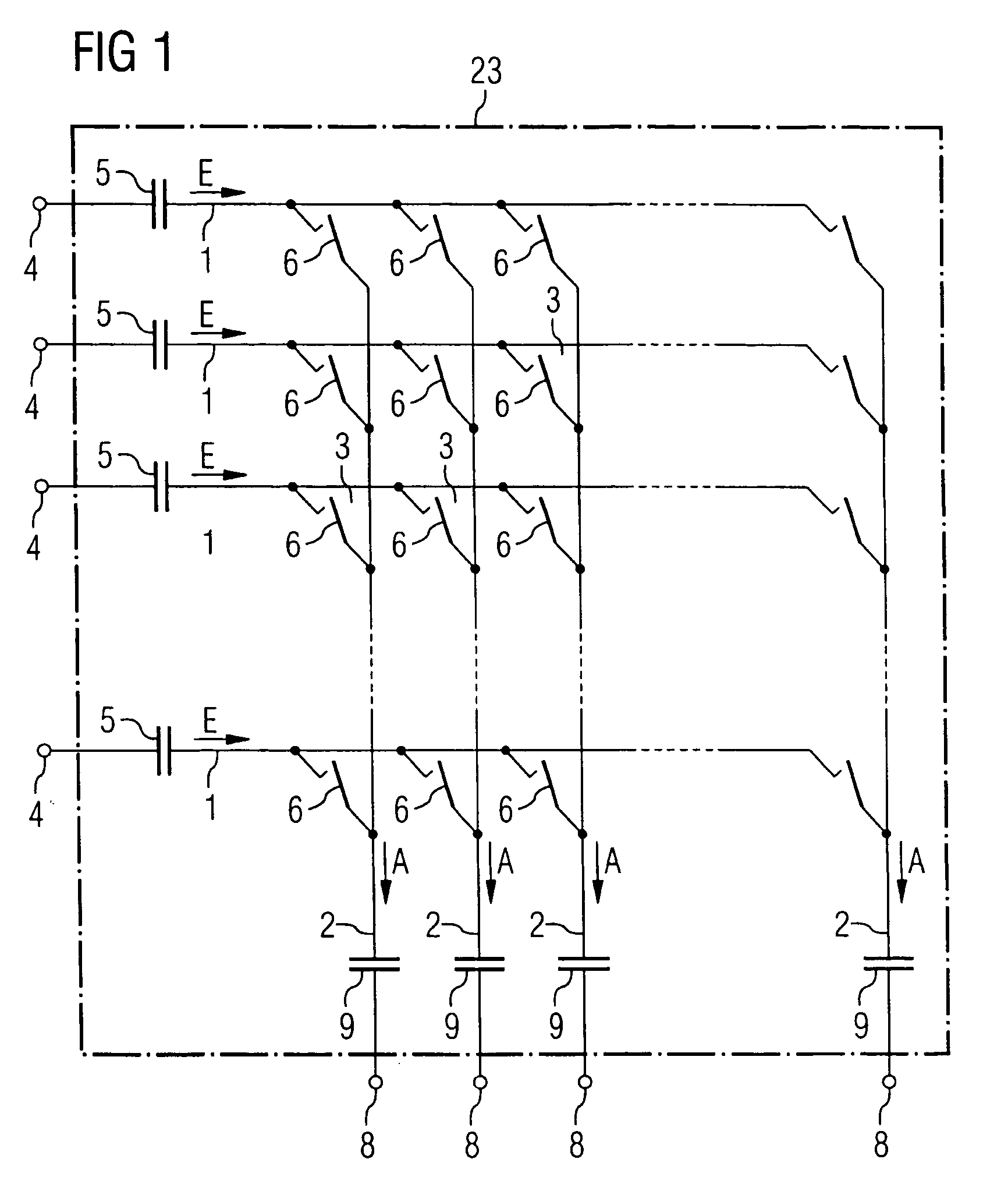
[0046]According to FIG. 1, a crossbar switch comprises a number of rows 1 and a number of columns 2. The rows 1 and the columns 2 intersect at crossing points 3.

[0047]Associated with each row 1 is a row input 4 that is connected with the respective row 1 via an intervening coupling capacitor 5. Input signals E can therefore be input to the rows 1 via the row inputs 4.

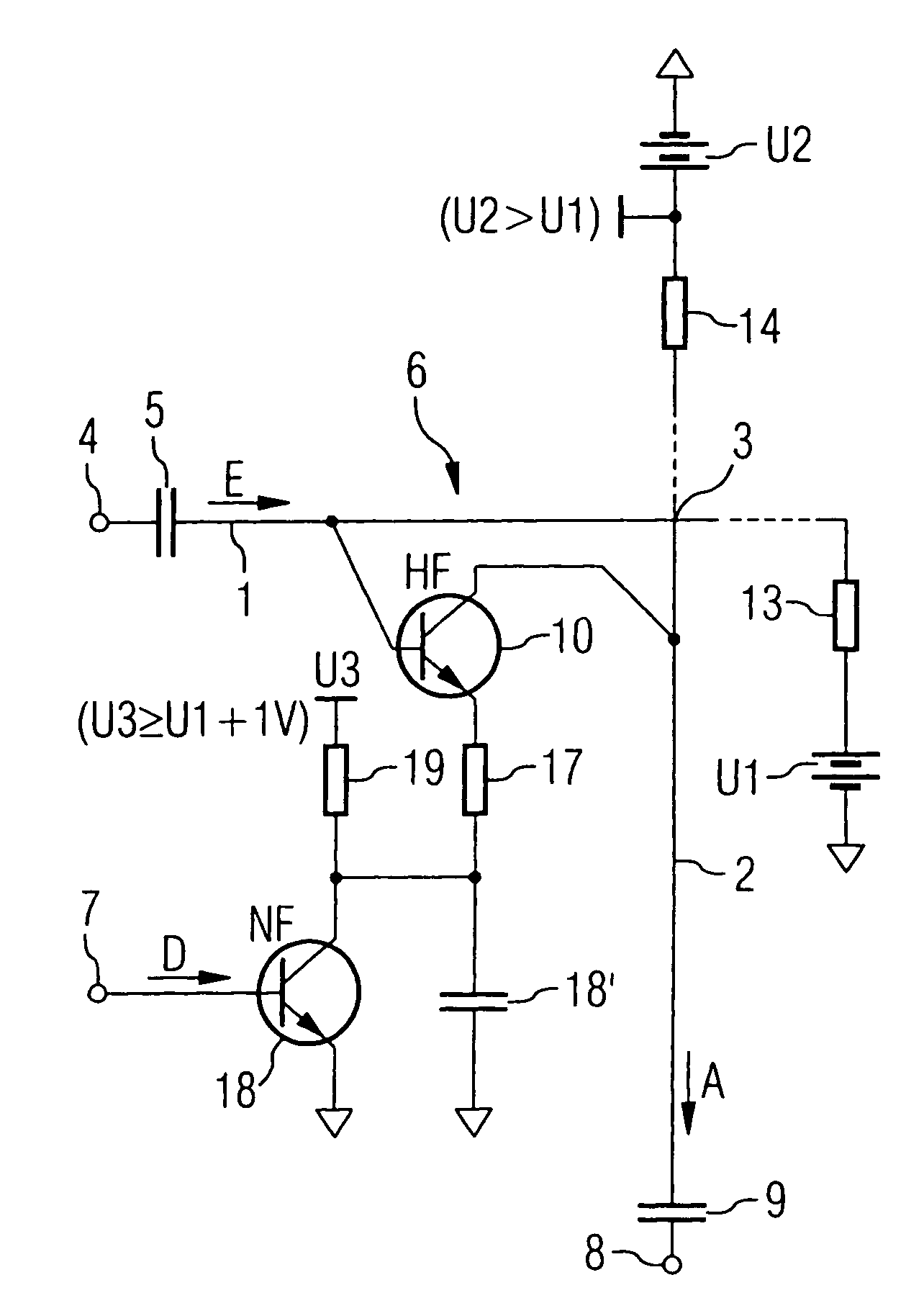
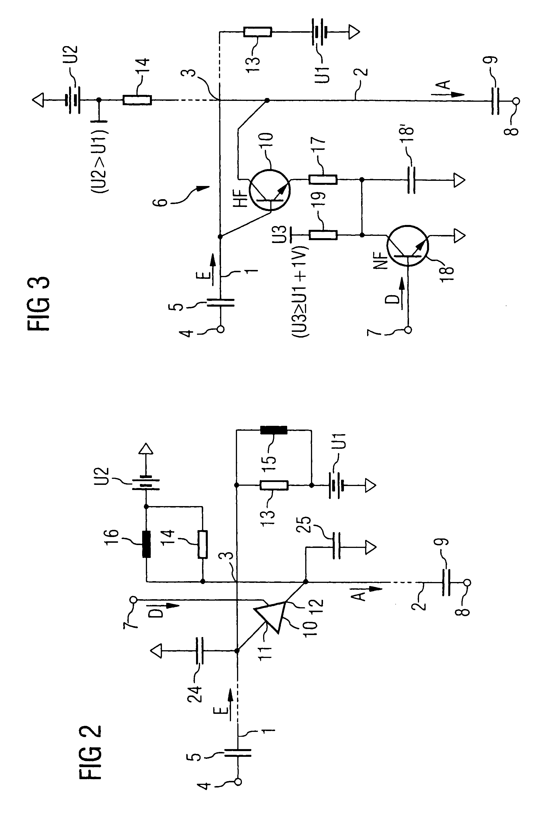
[0048]Controllable switch elements 6 are arranged at the crossing points 3. Via the switch elements 6, an input signal E that is supplied to a row 1 can be connected through to the column 2 which crosses this row 1 at this crossing point 3. However, the interconnection thereby ensues only when—see FIG. 2—an interconnection signal D is supplied to the respective crossing point 3 via a control input 7. A unique control input 7 is thereby associated with every crossing point 3. Thus every crossing point 3 can be activated independent of all other crossing points 3.

[0049]As a rule, an interconnection signal D is supplied at...


PUM


Abstract

A crossbar switch comprises a number of crossing points at which controllable switch elements are arranged, via which an input signal supplied to a row can be interconnected to a column intersecting this row at this crossing point when an interconnection signal is supplied to the respective setting parameter via a control input. The controllable switch elements comprise amplifier elements whose amplifier inputs are connected with the rows and whose amplifier outputs are connected with the columns. The amplifier elements are wired such that they only consume electrical energy when the interconnection signal is supplied to the respective crossing point.

Description

BACKGROUND OF THE INVENTION[0001]The present invention concerns a crossbar switch with a number of rows and a number of columns crossing the rows at crossing points, in which: a) an input signal is supplied to each row via a row input; b) controllable switch elements are arranged at the crossing points via which an input signal supplied to a row is connected through to the column crossing this row at this crossing point when a switching signal is supplied to the respective crossing point, and c) whereby a switched input signal is tapped as an output signal to each column via a column output.[0002]It is the object of a crossbar switch to interconnect a number of input signals to a number of outputs according to arbitrary specifications. The number of input signals is normally different than the number of output signals. In order to achieve such a switching capability, switch elements are arranged at crossing points, whereby each switch element can be switched individually and thus in...

Claims


Application Information

Patent Timeline
Patent Type & Authority Patents(United States)
IPC IPC(8): H01P1/10H01P1/15G11C17/00H03K17/62H04L12/56H04Q3/52
CPCH04L49/101
Inventor OPPELT, RALPHVESTER, MARKUS
Owner SIEMENS HEALTHCARE GMBH
Why Eureka
Try Eureka