System, method and computer program product for reducing quadratic phase errors in synthetic aperture radar signals

a synthetic aperture radar and quadratic phase error technology, applied in the field of systems and methods of processing synthetic aperture radar signals, can solve the problems of fine angular resolution, large-diameter antennas that are impractical to transport with any significant degree of mobility, and corrupt signal phase, etc., to achieve the effect of reducing quadratic phase errors

Inactive Publication Date: 2006-06-20
THE BOEING CO
View PDF20 Cites 30 Cited by
  • Summary
  • Abstract
  • Description
  • Claims
  • Application Information

AI Technical Summary

Benefits of technology

[0018]According to other aspects of the present invention, a system and computer program product for reducing quadratic phase errors are provided.

Problems solved by technology

The pulse-compression techniques provided significant improvement in the range resolution of the conventional radar systems, but fine angular resolution by the radiation of a narrow beam still required a large-diameter antenna which was impractical to transport with any significant degree of mobility.
As the SAR system operates, errors can be introduced into the system that, if not compensated for, will corrupt the signal phase, possibly to the extent that the resulting degraded image is of no practical use.
Such errors can be introduced from a variety of sources, including errors in motion measurements, inaccurate acceleration estimates and atmospheric / ionospheric propagation effects.
Such errors can be rather arbitrary and perhaps describable by a wide-band random process.
Conventional processing techniques, however, typically suffer from lack of accuracy in situations where target / clutter-to-noise ratios are low or there are several competing scatterers in a given range cell.

Method used


Image

  • System, method and computer program product for reducing quadratic phase errors in synthetic aperture radar signals
  • System, method and computer program product for reducing quadratic phase errors in synthetic aperture radar signals
  • System, method and computer program product for reducing quadratic phase errors in synthetic aperture radar signals

Examples


Embodiment Construction

[0028]The present invention now will be described more fully hereinafter with reference to the accompanying drawings, in which preferred embodiments of the invention are shown. This invention may, however, be embodied in many different forms and should not be construed as limited to the embodiments set forth herein; rather, these embodiments are provided so that this disclosure will be thorough and complete, and will fully convey the scope of the invention to those skilled in the art. Like numbers refer to like elements throughout.

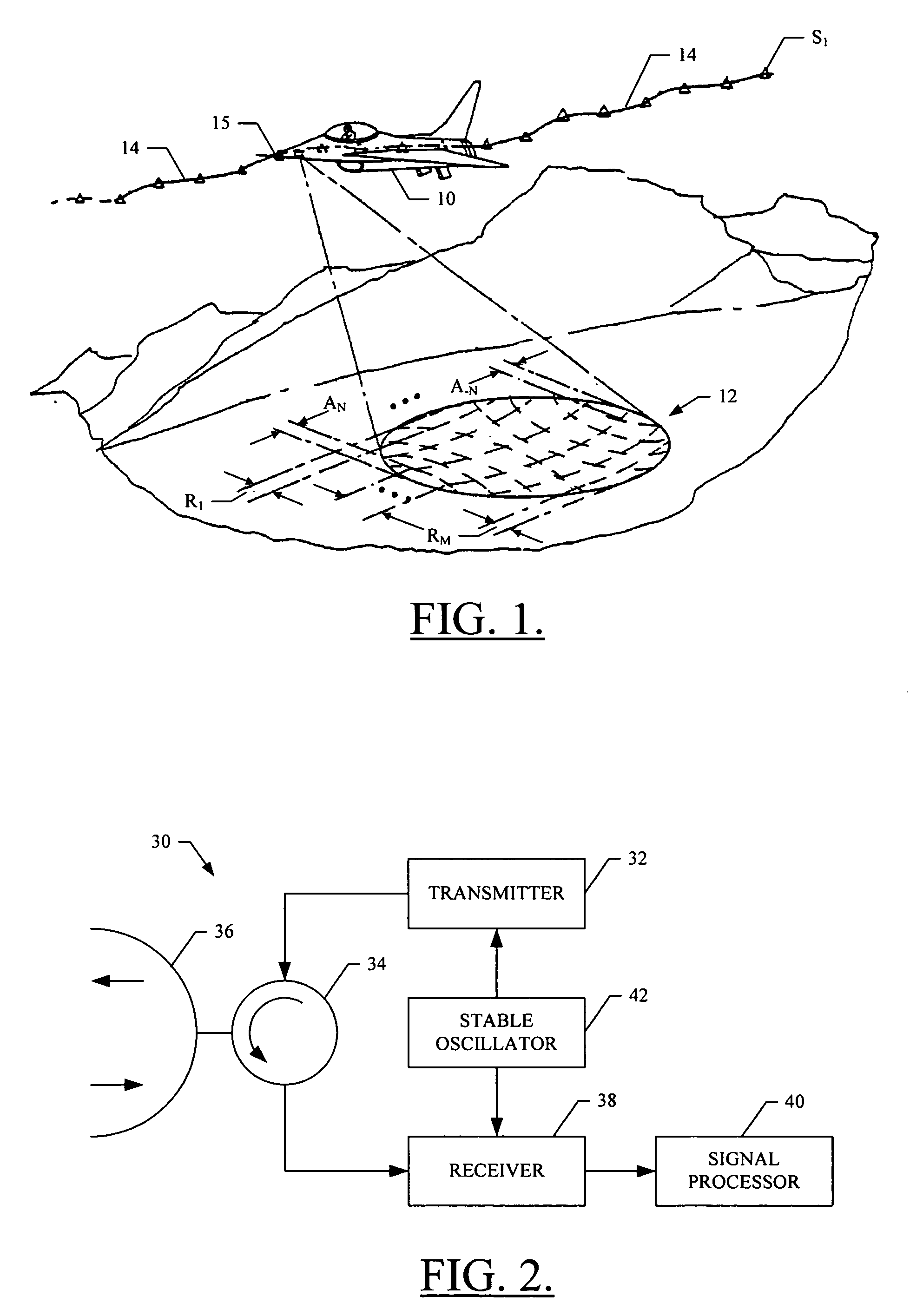
[0029]Referring to FIG. 2, a synthetic aperture radar (SAR) system therein is indicated generally by reference numeral 30. To briefly describe a conventional SAR system, a radar signal having a certain frequency is generated by a transmitter 32. The generated signal is sent to a duplexer 34 where it is further transmitted to an antenna 36. The signal is then transmitted from the antenna to a particular target region such as an area of terrain 12 (see FIG. ...


PUM


Abstract

A method is provided for reducing quadratic phase errors in synthetic aperture radar signals from a plurality of range lines where each range line includes a plurality of azimuth positions. The method includes receiving a plurality of slow-time samples representing radar signals for a plurality of azimuth positions for a plurality of range lines. A plurality of corrected samples and an initial quadratic phase error coefficient are identified based upon the slow-time samples. The corrected samples are processed according to a superresolution signal processing technique to thereby obtain a plurality of estimated Doppler frequencies for a plurality of point scatterers at each range line, after which a true signal for each range line is reconstructed based upon the plurality of estimated Doppler frequencies. A correction to the initial quadratic phase error coefficient is then obtained based upon the corrected samples, the true signals and the initial quadratic phase error coefficient.

Description

FEDERALLY SPONSORED RESEARCH OR DEVELOPMENT[0001]This invention was made with government support. The government may have certain rights in this invention.FIELD OF THE INVENTION[0002]The present invention relates generally to systems and methods of processing synthetic aperture radar signals and, more particularly, relates to systems and methods of autofocusing synthetic aperture radar signals utilizing superresolution processing to reduce quadratic phase errors.BACKGROUND OF THE INVENTION[0003]There has been a continuing effort to develop radar systems which are suitable for high-resolution applications, such as ground-mapping and air reconnaissance. Initially, this finer resolution was achieved by the application of pulse-compression techniques to conventional radar systems which were designed to achieve range resolution by the radiation of a short pulse, and angular, or azimuth, resolution by the radiation of a narrow beam. The pulse-compression techniques provided significant im...

Claims


Application Information

Patent Timeline
Patent Type & Authority Patents(United States)
IPC IPC(8): G01S13/90
CPCG01S13/9035G01S13/9019G01S13/904
Inventor ABATZOGLOU, THEAGENIS J.
Owner THE BOEING CO
Why Eureka
Try Eureka