
Printer and printing method for image-quality correction

Inactive Publication Date: 2006-06-20
FUJIFILM BUSINESS INNOVATION CORP
View PDF19 Cites 21 Cited by
  • Summary
  • Abstract
  • Description
  • Claims
  • Application Information

AI Technical Summary

Benefits of technology

[0019]According to the smoothing processing, occurrence of blurred portions in profile portions, such as line and character portions, can be prevented. In addition, thin-line patchiness is corrected. Therefore, the quality of printed images can be improved. For black and white pixel data representing halftone images, such as photographs, since they are not applicable to the irregular patterns to be smoothed, reduction in the quality level according to smoothing processing performed for halftone portions can be prevented.
[0048]V) Thin-line patchy patterns to thereby smooth the detected patterns.

Problems solved by technology

However, the method has the problem of not being able to reproduce gradations of halftone images, such as photographs.
However, in the dither method, since the number of gradations is determined according to the size of a matrix, a problem is arisen in that the resolution of a high-contrast line or character image is reduced.
In addition, with a matrix of which the size is reduced, gradient characteristics sharply vary to develop defects such as pseudoprofiles, thereby reducing the print quality level.
However, this arises the problem of reducing the resolution of the print portions of line images and characters.
As described above, in the area gradation representation methods, the number of gradations in one pixel greatly depends on the basic pixel size; in proportion to the increase in the resolution, the difficulty increases in the representation of the number of intrapixel gradations through a practically-used printer.
Therefore, the reduction level in resolution is relatively low.
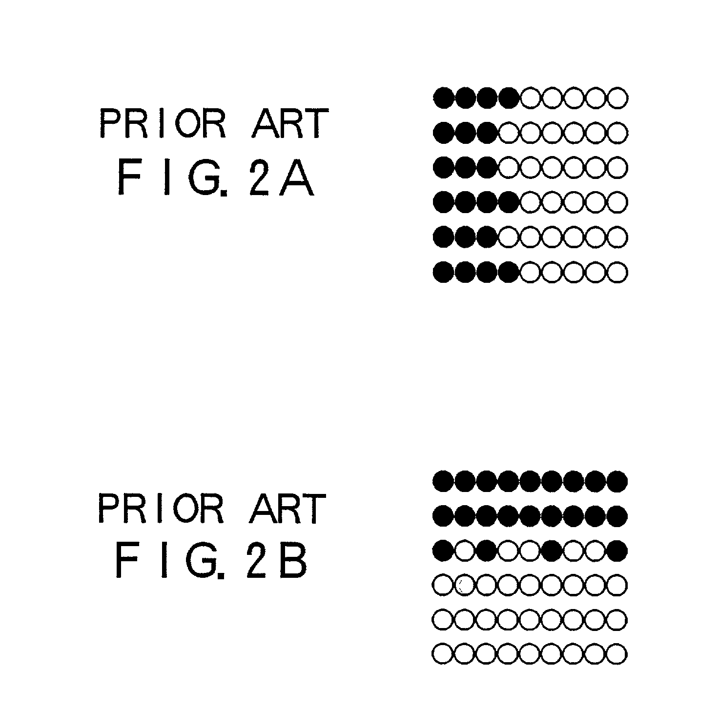
However, in binary processing according to the above-described conventional error-variance method, error variance is also performed for profile portions of high-contrast line images and character images.
Therefore, in the binary processing of gray-scale fields in the profile portions to which quantization errors are distributed, irregularities are generated in border fields between black and white lines.
In addition, for thin lines and low-density color lines, since MTF of multivalue image data is low.
Therefore, as in the cases of a vertical line in FIG. 3A, a horizontal line in FIG. 3B, and a slanting line in FIG. 3C, defects are caused such that the lines are patchy and discontinuous.
However, the smoothing processing is not effective in the correction of irregularities and patchiness in black and white pixel data binary-coded by the error-variance method.
Therefore, the image quality is not improved thereby.
In this case, the smoothing processing gives adverse effects.
As a result, the smoothing processing causes problems in that gradient characteristics are impaired; and reversed gradation, pseudo profiles, and linear and streaky images are generated in halftone images, thereby significantly degrading the image quality level.
Therefore, when the print image is visually observed, individual black pixels cannot be easily identified.
In addition, the density of gray in the highlight portion cannot be easily recognized.
However, the mechanism is expensive, requires a high cost in precision adjustment and the like.
However, the method has disadvantages in that processing is significantly complicated, and the resolution is significantly reduced when a document, such as an office document, having containing high-contrast images is processed.
Therefore, for an image of a character, a slanting line, or the like, image defects, such as streaky indented portions and aberrant portions, and the like become conspicuous.
An additional disadvantage is that one thin line to be represented can be omitted because of the line-unit removal, and there may even be a terrible case where represented characters cannot be readable.
Also in this case, however, patchiness in thin lines and irregularities caused by flickered lines appear noticeably on an output image.

Method used


Image

  • Printer and printing method for image-quality correction
  • Printer and printing method for image-quality correction
  • Printer and printing method for image-quality correction

Examples


Embodiment Construction

(Configuration of Apparatus)

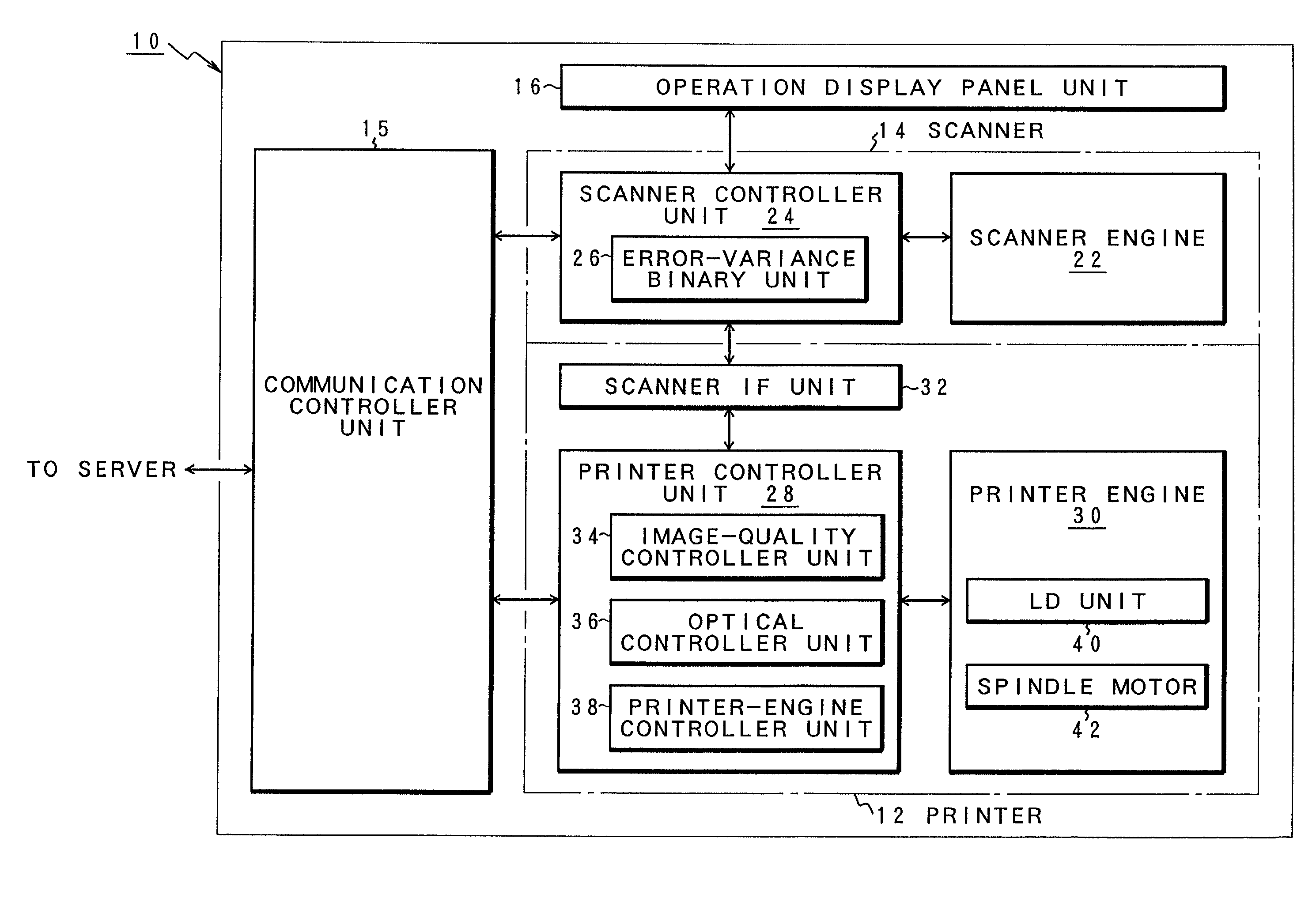
[0121]FIG. 6 is a front view of a composite-image printing apparatus 10 to which a printer and a printing method of the present invention are applied. FIG. 7 is a right-side view of the composite-image printing apparatus 10 shown in FIG. 1, and FIG. 8 is a plan view thereof. In FIG. 6, the composite-image printing apparatus 10 is configured to include a printer 12, a scanner 14, an operation display panel unit 16, and a paper-tray section 18 (which hereinbelow will simply be referred to as a “paper tray”). The composite-image printing apparatus 10 is connected to a server (not shown) via a local area network (LAN)(not shown). As described above, client terminals (not shown) are connected via the LAN, and in addition, external client terminals (not shown) are connected to the server via a network, so-called Intranet (not shown). The composite-image printing apparatus 10, which is thus connected to the server via the LAN, includes a photocopy reproduction m...


PUM


Abstract

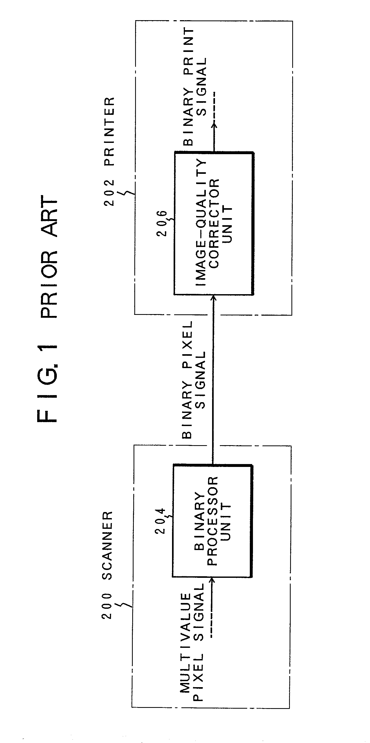
A printer performs printing after appropriately correcting irregularities, thin-line patchiness, and isolated pixels. A first image-quality corrector unit detects slanting-line irregularities represented by the black and white pixel data generated through binary processing according to a method other than the error-variance method to thereby perform smoothing processing therefor. A second image-quality corrector unit detects defects such as irregularities and patchiness specific to the binary processing according to the error-variance method to thereby perform smoothing processing therefor. A third image-quality corrector unit detects isolated pixels in gray fields that are specific to the binary processing according to the error-variance method to thereby distribute the isolated pixels to peripheral pixels. When an original image is reduced in size according to pixel-removal prior to the binary processing, the pixel-removal is not performed if a gradient variation is relatively great with respect to peripheral pixels.

Description

[0001]This application is a continuation of PCT / JP99 / 05073 filed Sep. 17, 1999TECHNICAL FIELD[0002]The present invention relates to a printer and a printing method for printing binary black and white pixel data converted from multivalue image data (“image data” hereinbelow may be referred to as “video data”) representing combined images of halftone-gradation images (such as photographs), characters, and lines. Particularly, the invention relates to a printer and a printing method for printing black and binary white pixel data after correcting defects such as irregularity and omission in the binary black and white pixel data converted by an error-variance method from multivalue image data.BACKGROUND ART[0003]Conventionally, there are various types of apparatuses and systems having an image processing mechanism. They include facsimile machines, photocopy reproduction machines, documentation-filing systems, and desk-top publishing systems. These apparatuses and systems perform processi...

Claims


Application Information

Patent Timeline
IPC IPC(8): H04N1/60H04N1/409H04N1/405
CPCH04N1/4092H04N1/4052
Inventor TAKASHIMIZU, YOSHIHIRO
Owner FUJIFILM BUSINESS INNOVATION CORP
Learn More