Optical recording apparatus and optical recording/reproducing apparatus

Inactive Publication Date: 2006-06-20
FUJIFILM BUSINESS INNOVATION CORP
View PDF3 Cites 35 Cited by
  • Summary
  • Abstract
  • Description
  • Claims
  • Application Information

AI Technical Summary

Benefits of technology

[0020]In the optical recording/reproducing apparatus of the invention, since the signal light and the reference light whose polarization directions are crossed at right angles with each other are generated from the light incident from the single light source, the signal light and the reference light are always coaxial, optical axes of the signal light and the reference light are never shifted even if the vibration is ap

Problems solved by technology

However, it is a problem that the hologram recording by the two-beam interference is susceptible to vibration, and the recording must be carried out while the recording medium is stopped.
There are other problems that an optical system becomes complicated and a drive apparatus is enlarged and the like.
1) The reference light is refl

Method used


Image

  • Optical recording apparatus and optical recording/reproducing apparatus
  • Optical recording apparatus and optical recording/reproducing apparatus
  • Optical recording apparatus and optical recording/reproducing apparatus

Examples


first embodiment

[First Embodiment]

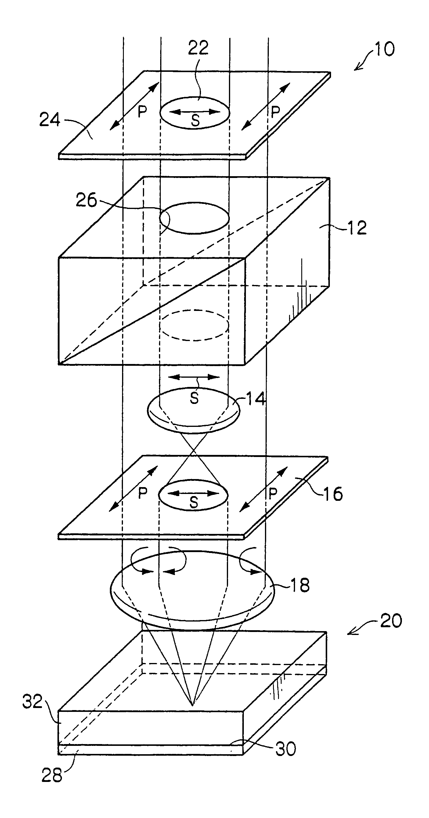
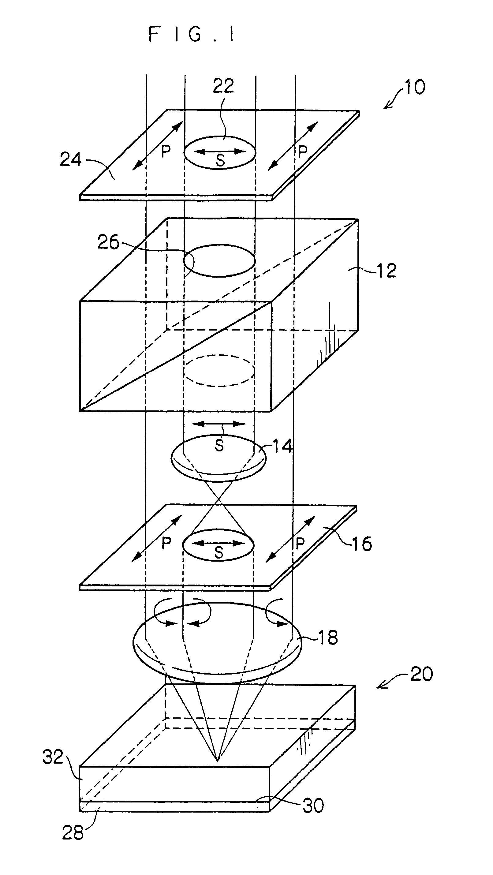
[0029]As shown in FIG. 1, an optical recording apparatus according to a first embodiment of the present invention includes a spatial light modulator 10 which modulates coherent light from a light source (not shown) to generate signal light and reference light whose polarization directions are crossed at right angles with each other, a polarizing beam splitter 12 which is arranged only on a light path of the generated signal light and separates a predetermined polarization component, a light diffuser 14 which is arranged only on a light path of the generated reference light and is a holographic optical element controlling a wavefront of the reference light, a quarter wavelength plate 16 which converts the signal light transmitted through the polarizing beam splitter 12 and the reference light transmitted through the light diffuser 14 into circularly polarized light, and a condenser lens 18 which condenses the generated circularly polarized light into a predetermined...

second embodiment

[Second Embodiment]

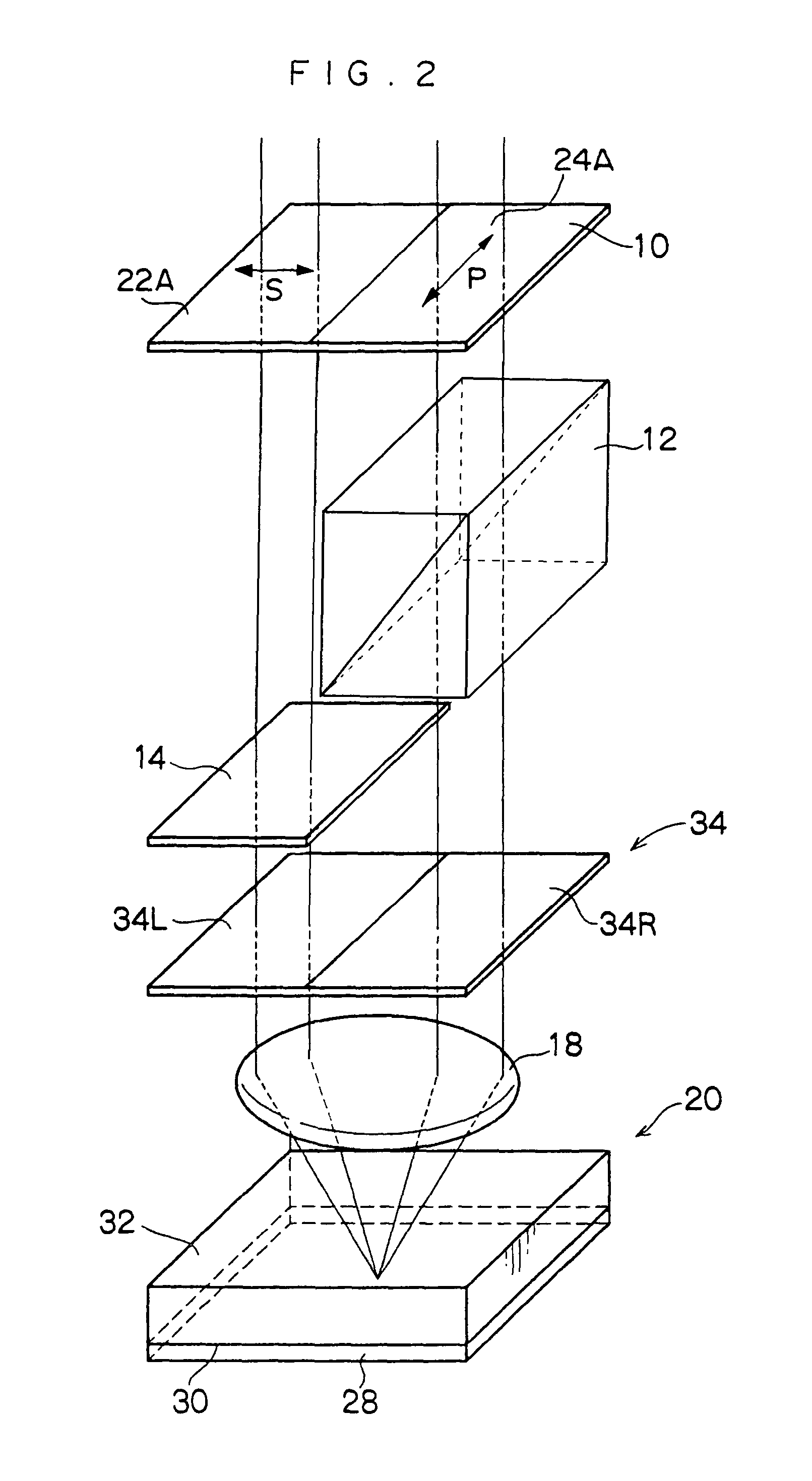
[0044]As shown in FIG. 2, an optical recording apparatus according to a second embodiment of the present invention has the same configuration for the optical recording apparatus according to the first embodiment except that a left half of the spatial light modulator 10 is set to a reference light area 22A, a right half of the spatial light modulator 10 is set to a signal light area 24A, and a two-split azimuth rotator plate 34 is arranged so as to correspond to each area instead of the quarter wavelength plate. Accordingly, the same component is indicated with the same reference numeral and its description is omitted.

[0045]In the second embodiment, light which has passed through the left-half area 22A of the spatial light modulator 10 is set to s-polarized reference light, and light which has passed through the right-half area 24A of the spatial light modulator 10 is set to p-polarized reference light. Therefore, in the case of using a liquid crystal panel for a p...


PUM


Abstract

An optical recording/reproducing apparatus having excellent resistance against vibration and noise is provided. In recording, coherent light is polarization-modulated with a spatial light modulator to generate signal light and reference light whose polarization directions are crossed at right angles with each other. The signal light permeates a polarizing beam splitter, and is incident to a quarter wavelength plate. The reference light passes through a passing hole, is diffused by a light diffuser and is incident to the quarter wavelength plate. The reference and signal light are converted into circularly polarized light which revolve in directions opposite to each other and condensed by a condenser lens, and then a predetermined area of an optical recording medium is irradiated with the reference and signal light. Thus, the reference and signal light are generated by modulating the incident light from the same light source and are coaxially incident to the polarizing beam splitter.

Description

CROSS REFERENCE TO RELATED APPLICATION[0001]This application claims priority under 35 USC 119 from Japanese Patent Application No. 2003-081456, the disclosure of which is incorporated by reference herein.BACKGROUND OF THE INVENTION[0002]1. Field of the Invention[0003]The present invention relates to an optical recording apparatus and an optical recording / reproducing apparatus, and particularly relates to an optical recording apparatus for recording information in an optical recording medium as a hologram and an optical recording / reproducing apparatus for recording information in an optical recording medium as a hologram and for reproducing the recorded information.[0004]2. Description of the Related Art[0005]Generally, an incident angle for diffracting light must be more precise as a hologram becomes thicker. The diffracted light disappears even if the incident angle is slightly shifted from Bragg condition. In a volume holographic memory, an angle multiplexing method utilizes this ...

Claims


Application Information

Patent Timeline
IPC IPC(8): G03H1/12G11B7/0065G11B7/125G11B7/135G11B7/245G11B7/246
CPCG11B7/0065G11B7/128G11B7/1353G11B7/1356G11B7/1369G11B7/245G03H2222/31G11B7/2535G11B7/2467G11B7/25G11B7/2531G11B7/2533G11B7/2534
Inventor KAWANO, KATSUNORIMINABE, JIROMARUYAMA, TATSUYAYASUDA, SHINMATSUI, NORIEISHII, TSUTOMUHAMA, KAZUHIRO
Owner FUJIFILM BUSINESS INNOVATION CORP
Why Eureka
Try Eureka