Methods and apparatus for injecting cleaning fluids into combustors

a technology of cleaning fluid and combustors, which is applied in the direction of lighting and heating apparatus, machines/engines, vehicle cleaning, etc., can solve the problems of carbon build-up, adversely affect engine performance, and build-up, and achieve the effect of eliminating damage to other areas of the combustor

Inactive Publication Date: 2006-06-27
GENERAL ELECTRIC CO
View PDF54 Cites 36 Cited by
  • Summary
  • Abstract
  • Description
  • Claims
  • Application Information

AI Technical Summary

Benefits of technology

[0005]In another aspect, a spray nozzle assembly for injecting water into a gas turbine engine combustor is provided. The spray nozzle assembly includes a nozzle stem, a mounting flange, and a popet nozzle. The nozzle stem comprises an inlet and an outlet. The inlet is configured to couple in flow communication to a high-pressure water source. The mounting flange circumscribes the nozzle stem adjacent the nozzle outl...

Problems solved by technology

Over time, the carbon may build up and adversely effect engine performance.
More specifically, carbon build-up may adversely effect airflow characteristics within the combustor and/or skew the accuracy and margin of performance instruments positioned within the engine flowpath.
However, because of accessibility limitations, the vent...

Method used


Image

  • Methods and apparatus for injecting cleaning fluids into combustors
  • Methods and apparatus for injecting cleaning fluids into combustors
  • Methods and apparatus for injecting cleaning fluids into combustors

Examples


Embodiment Construction

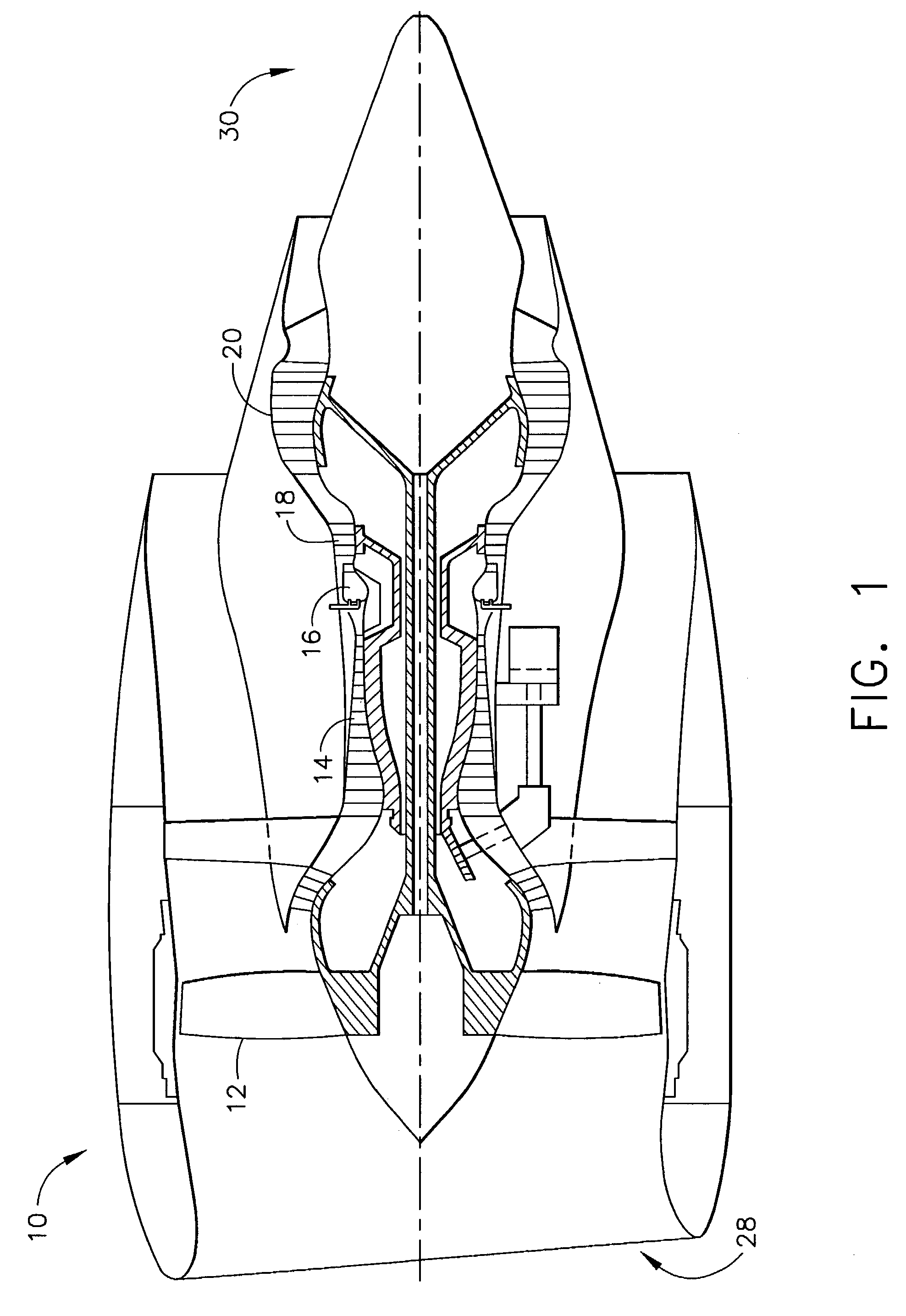
[0012]FIG. 1 is a schematic illustration of a gas turbine engine 10 including a fan assembly 12, a high pressure compressor 14, and a combustor 16. Engine 10 also includes a high pressure turbine 18, a low pressure turbine 20, and a booster 22. Fan assembly 12 includes an array of fan blades 24 extending radially outward from a rotor disc 26. Engine 10 has an intake side 28 and an exhaust side 30. In one embodiment, the gas turbine engine is a CF-34 engine available from General Electric Company, Cincinnati, Ohio.

[0013]In operation, air flows through fan assembly 12 and compressed air is supplied to high pressure compressor 14. The highly compressed air is delivered to combustor 16. Airflow (not shown in FIG. 1) from combustor 16 drives turbines 18 and 20, and turbine 20 drives fan assembly 12.

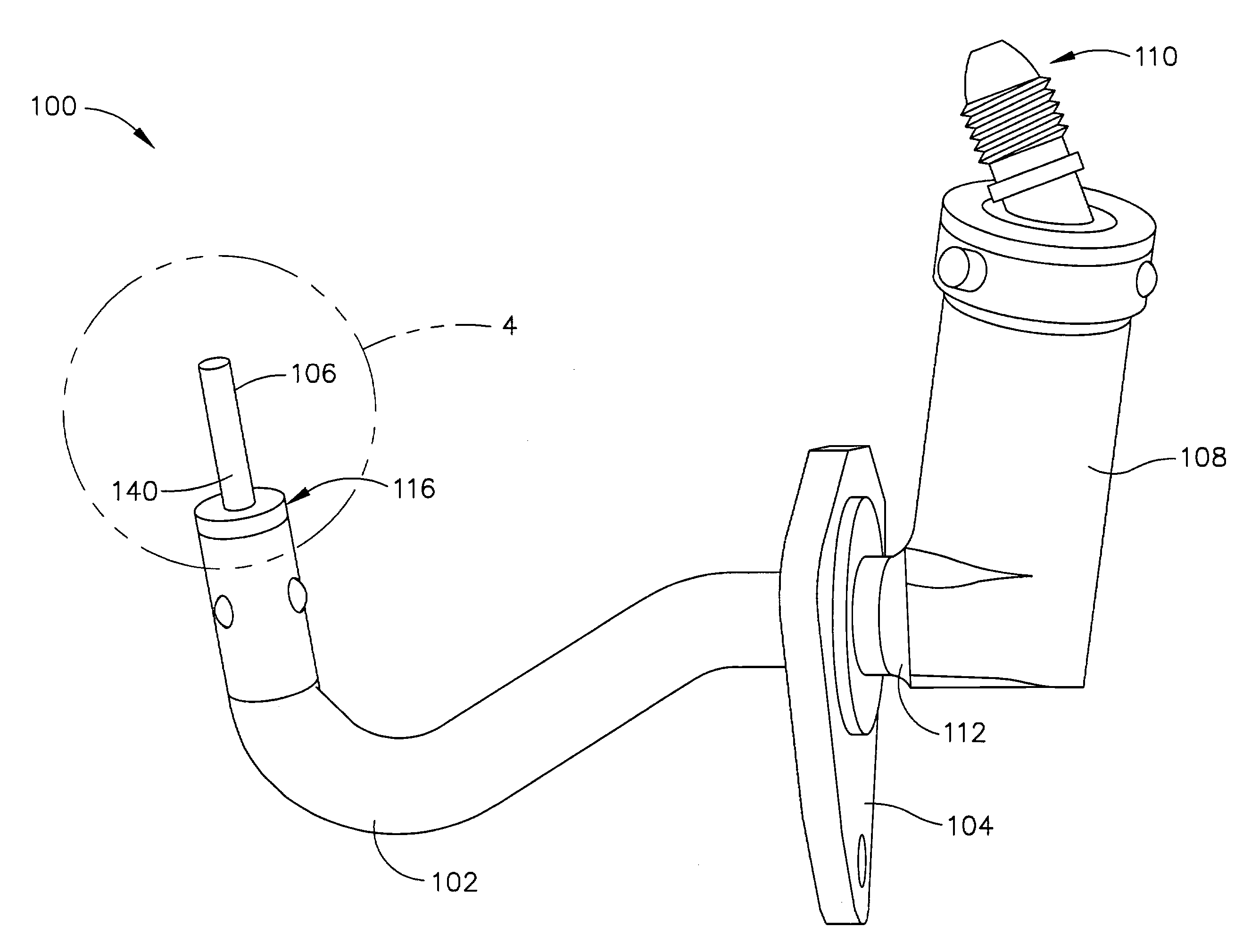
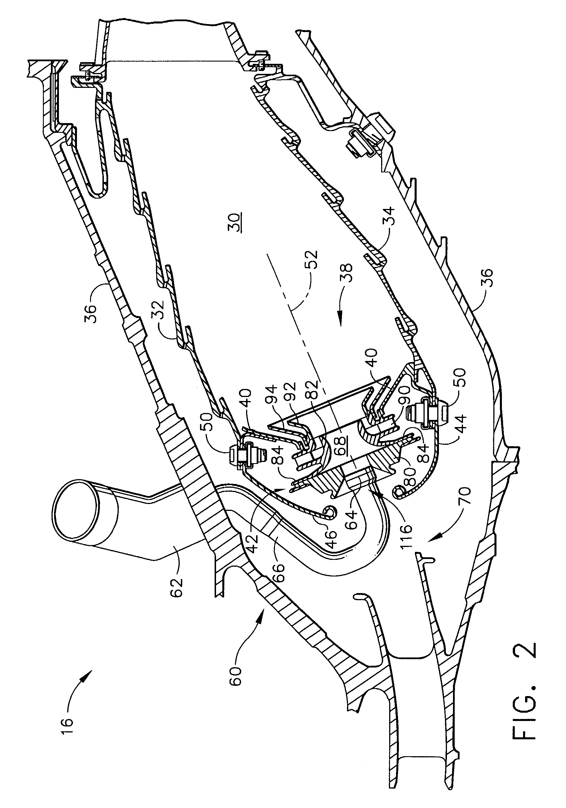
[0014]FIG. 2 is a cross-sectional view of an exemplary combustor 16 for use with a gas turbine engine, similar to engine 10 shown in FIG. 1. More specifically, in the exemplary embodiment, com...


PUM


Abstract

A method details injecting water into a gas turbine engine to facilitate cleaning an inner surface of a combustor. The method comprises removing an axial fuel injector from the combustor, wherein the fuel injector includes a nozzle stem, and inserting a spray nozzle assembly into a fuel injector opening created within the combustor when the fuel injector was removed, wherein the spray nozzle assembly includes a popet nozzle that is coupled to a nozzle stem that is shaped substantially identically to the fuel injector nozzle stem removed from the combustor. The method also comprises coupling the spray nozzle assembly to the combustor such that the popet nozzle is inserted substantially concentrically into the combustor, and injecting water into the combustor through the spray nozzle assembly.

Description

BACKGROUND OF THE INVENTION[0001]This application relates generally to gas turbine engine combustors and, more particularly, to methods and apparatus for injecting cleaning fluids under pressure into assembled and on wing gas turbine engine combustors to facilitate removing build-up that degrades performance.[0002]Gas turbine engines typically include a compressor for compressing air which is mixed with a fuel and channeled to a combustor wherein the mixture is ignited within a combustion chamber for generating hot combustion gases. At least some known combustors include a dome assembly, a cowling, and liners to channel the combustion gases to a turbine, which extracts energy from the combustion gases for powering the compressor, as well as producing useful work to propel an aircraft in flight or to power a load, such as an electrical generator. The liners are coupled to the dome assembly with the cowling, and extend downstream from the cowling to define the combustion chamber. At l...

Claims


Application Information

Patent Timeline
IPC IPC(8): F02C7/30B08B9/032F01D25/00F02C7/00F23J3/02F23R3/00
CPCF01D25/002F23R3/00F23J3/02F05D2220/32
Inventor REBACK, SCOTT MITCHELLSEBEIKA, STEPHEN THOMAS
Owner GENERAL ELECTRIC CO
Why Eureka
Try Eureka