Powered lifting apparatus using multiple booms

a technology of lifting apparatus and boom, which is applied in the direction of lifting equipment, load-engaging elements, prefabricated buildings, etc., can solve the problems of high cost of lifting very large objects such as chemical process vessels, large equipment, time-consuming and expensive operation, and reduce power requirements, costing the effect of transportation and assembly

Inactive Publication Date: 2006-06-27
KHACHATURIAN JON E
View PDF32 Cites 23 Cited by
  • Summary
  • Abstract
  • Description
  • Claims
  • Application Information

AI Technical Summary

Benefits of technology

[0014]The present invention provides an improved method and apparatus for lifting multi-ton packages such as chemical vessels, pre-fabricated structures, equipment packages and the like. This invention requires no counterweights, which can be costly to transport and assemble, because it operates using leverage against itself. Power requirements are reduced using this invention, as the power supply is the horizontal extendable member which carries only the horizontal component of boom load. Ground pressure, a significant problem associated with heavy loads, can be reduced by an order of magnitude by dividing the weight onto four evenly loaded carriages instead of eccentrically loading one crane matrix.

Problems solved by technology

In the construction industry and at industrial plants, there is great expense associated with the lifting of very large objects such as chemical process vessels, large pieces of equipment, pre-fabricated buildings and the like.
Such objects are typically lifted with one or more very large and expensive devices such as high capacity lifting booms or cranes.
This is a very time consuming and expensive operation costing millions of dollars, even for one lift in some cases where the load is very large (e.g., several thousand tons).
Scheduling of large equipment can be critical, due to the limited number of very large capacity cranes world-wide and the time restraints and deadlines associated with plant expansions, turnarounds and renovations.
Some of the problems with the lifting of very large objects is the mobilization cost, the complex rigging that must be accomplished timely, and demobilization once the lift is completed.
Huge counterweights are required to equally distribute load, especially if soil conditions are less than perfect.
Another problem with crane lifts is that of a rotation or shifting of the object being lifted so that it hits the crane.
During a lift, a crane boom is under such stress, that catastrophic failure can result when the object being lifted even lightly hits the crane.
Cranes can also fail if the object being lifted moves (e.g., with wind load) out away from the center of the hook.

Method used


Image

  • Powered lifting apparatus using multiple booms
  • Powered lifting apparatus using multiple booms
  • Powered lifting apparatus using multiple booms

Examples


third embodiment

[0079]FIGS. 10–16 show the apparatus of the present invention designated generally by the numeral 10C in FIGS. 10, 11, 12, 13, and 14.

[0080]Lifting apparatus 10C is shown lifting a vessel 59 from a generally horizontal position as shown in FIG. 10 to the vertical position shown in FIG. 14. FIGS. 11, 12, and 13 show the vessel 59 in an inclined position as occurs during the lift.

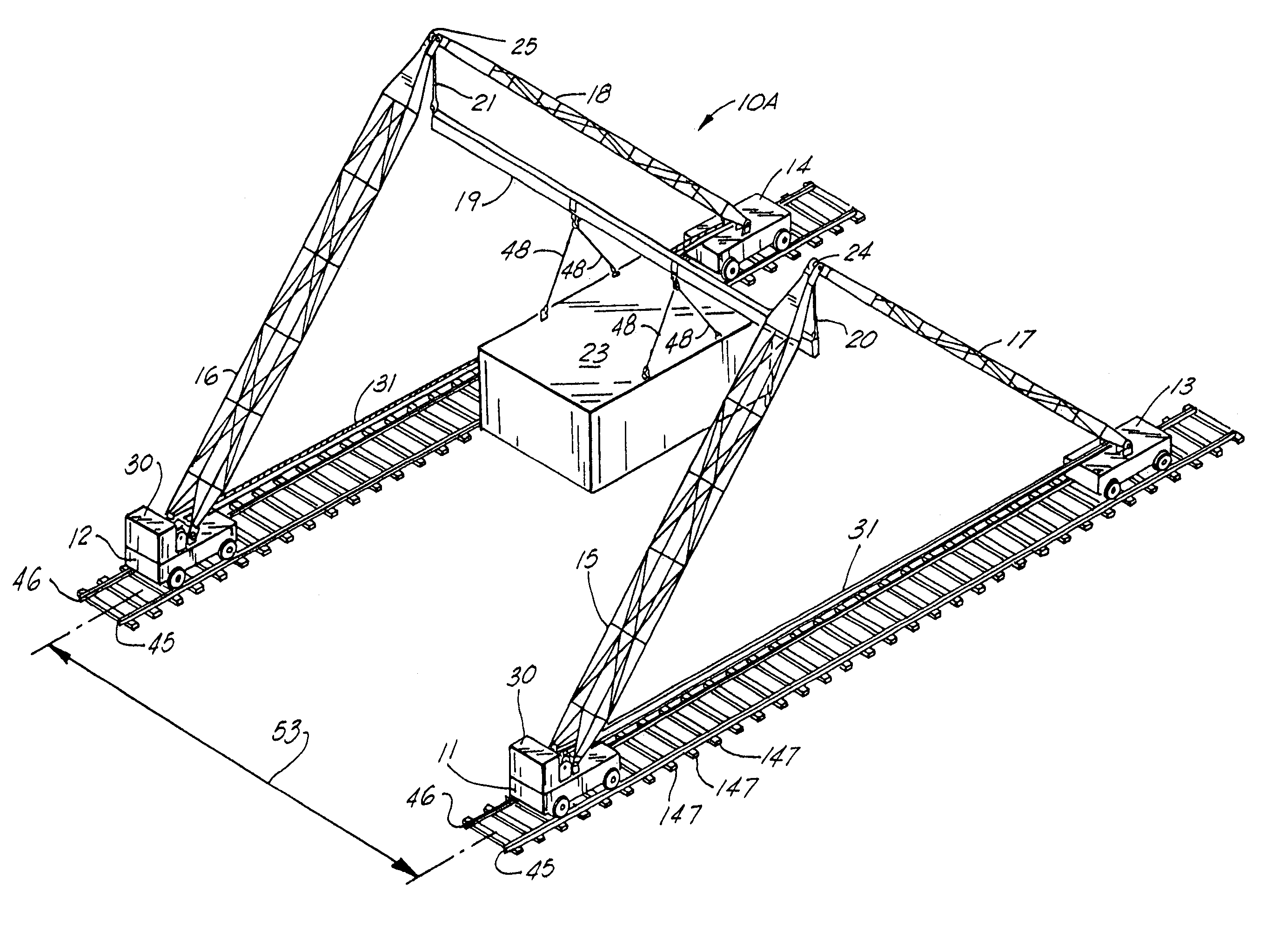
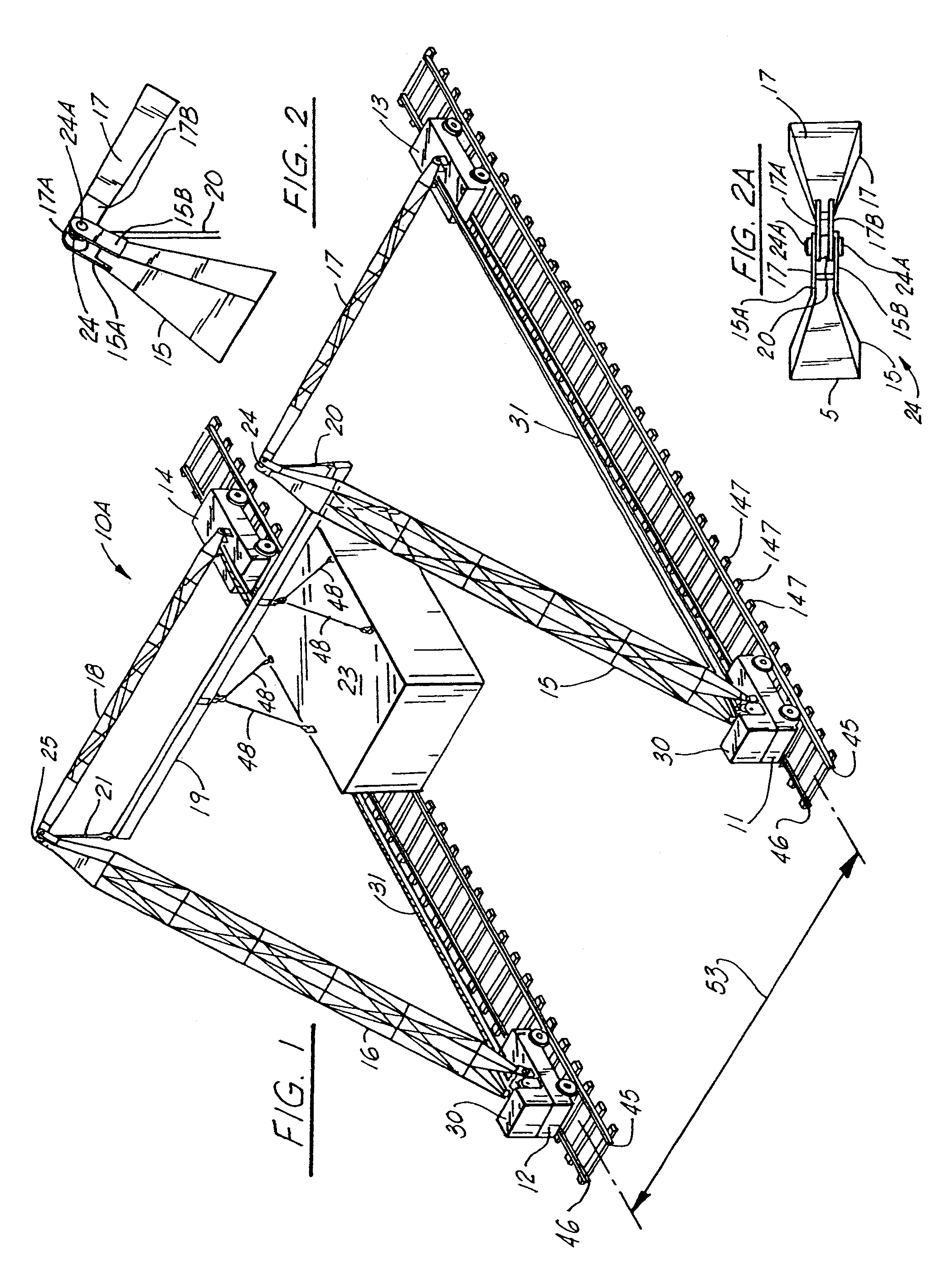
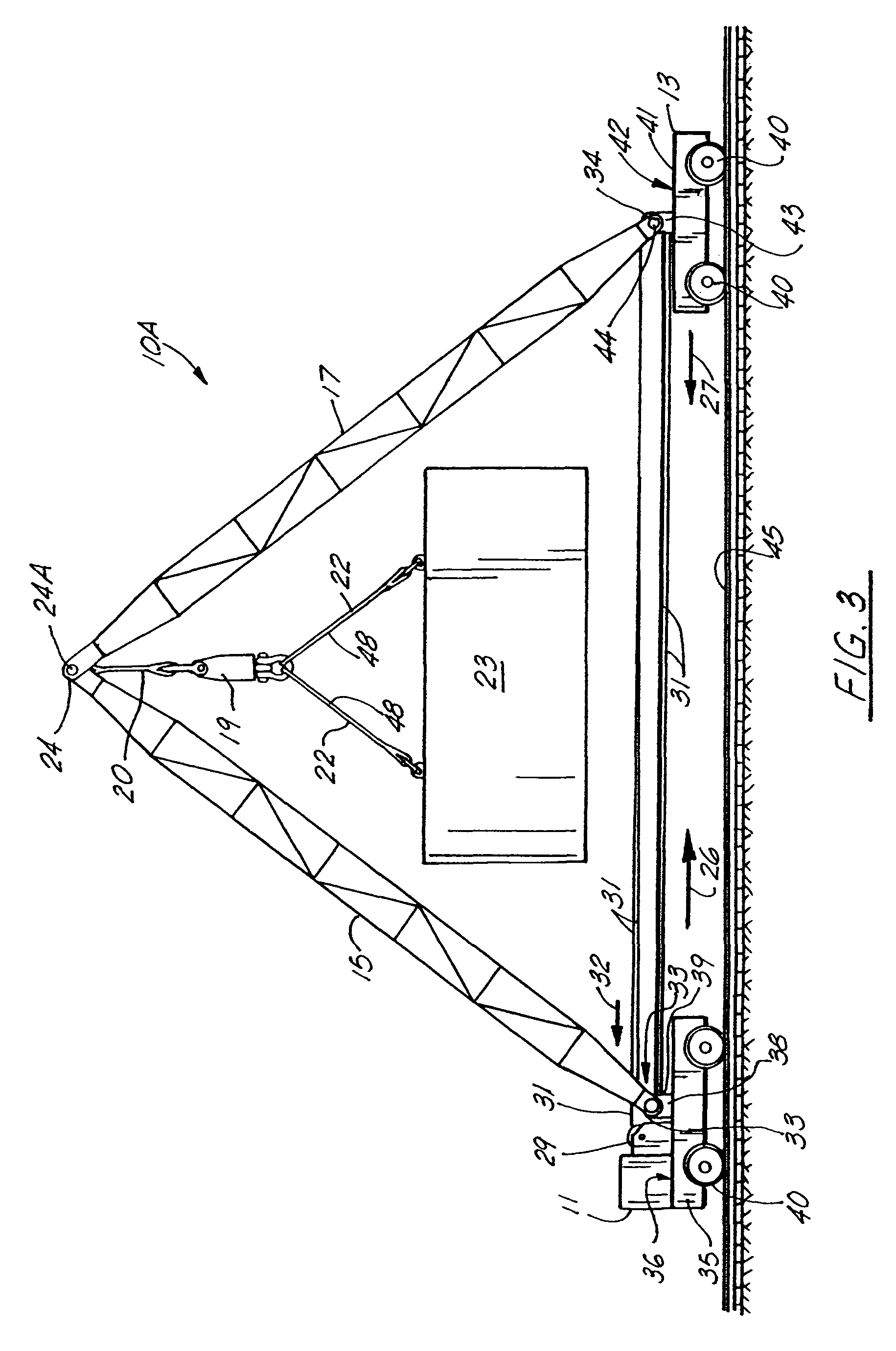
[0081]As with the first and second embodiments of FIGS. 1–9, lifting apparatus 10C includes a plurality of carriages that support booms in an opposed and parallel relationship. As with the embodiments of FIGS. 1–9, a pair of booms are pinned and supported respectively by a pair of carriages. A second pair of carriages and respective booms is positioned next to and generally parallel to the first pair of carriages and booms. This arrangement can be seen in FIGS. 10–14 in the drawings.

[0082]A first pair of carriages 61, 62 are mounted upon supports such as rails 60 (see FIG. 15). The carriage 61 supports a boom...

sixth embodiment

[0101]In FIGS. 30–35, the apparatus of the present invention is shown, designated generally by the numeral 10E in FIGS. 30–33 and 35.

[0102]Each of the booms 107, 108 has a carriage 145 that includes an upper deck 146 that supports winch pedestal 171 (FIG. 34). Winch pedestal 171 supports winch 162 that has a winch cable 163. In the drawings, the boom 107 has a winch 162 with winch cable 163. The boom 108 has a winch 162 with a winch cable 164 (FIG. 31). The winch cables 163, 164 extend upwardly along each boom 107, 108 respectively as shown in FIG. 35 to a position just below lower brace 168. At the intersection of lower brace 168 and boom 107, a pulley 165 is provided through which cable 163 passes. Similarly, cable 164 extends from winch 162 upwardly along the length of boom 108 to a position next to lower brace 168 and is rigged to pulley 166. In FIG. 32, the winch cable 163 extends from pulley 165 diagonally to boom 106 and connects to cross brace 122. Similarly, cable 164 exten...


PUM


Abstract

A lifting apparatus includes a plurality of preferably four carriages, each carriage supporting a lifting boom. Two booms are pinned together to define a first pair, a second two booms being pinned together to define a second pair. Each pair of booms and connected carriages are placed on a preferably common travel path. Rigging can include a horizontal beam that extends between the first pair of booms and the second pair of booms. The beam can be attached to the pinned connection of each pair of booms with a sling. A powered motor-driven winch is used to power a cable that is wound between sheaves on the lower end portions of a pair of booms that are connected together. During use, the winches are simultaneously or nearly simultaneously operated to elevate the first pair of the booms and the second pair of booms at about the same time. The horizontal beam that spans in between booms is elevated. Packages can be lifted with the horizontal beam by depending one or more slings from the horizontal beam to the package to be lifted. The apparatus can use carriages that are provided with wheels that travel on rails. Carriages can use rubber tires, or can be sled or skid-mounted without the use of wheels or tires.

Description

CROSS-REFERENCE TO RELATED APPLICATIONS[0001]This is a continuation-in-part of U.S. Ser. No. 09 / 808,764, filed Mar. 15, 2001, now U.S. Pat. No. 6,601,717 which is a continuation-in-part of U.S. Ser. No. 09 / 460,479, filed Dec. 14, 1999, now U.S. Pat. No. 6,213,319 which is a continuation of U.S. patent application Ser. No. 08 / 987,416 filed Dec. 9, 1997 (now U.S. Pat. No. 6,000,562), which is a continuation-in-part of U.S. patent application Ser. No. 08 / 780,846, filed Dec. 9, 1996, now U.S. Pat. No. 5,836,436 all of which are incorporated herein by reference.STATEMENT REGARDING FEDERALLY SPONSORED RESEARCH OR DEVELOPMENT[0002]Not applicableREFERENCE TO A “MICROFICHE APPENDIX”[0003]Not applicableBACKGROUND OF THE INVENTION[0004]1. Field of the Invention[0005]The present invention relates to heavy equipment, and more particularly to heavy lifting equipment that is used in commercial applications for lifting very heavy multi-ton objects that can weigh as much as several thousand tons. Ev...

Claims


Application Information

Patent Timeline
Patent Type & Authority Patents(United States)
IPC IPC(8): B66C23/50
CPCB66C19/02B66C5/02
Inventor KHACHATURIAN, JON E.
Owner KHACHATURIAN JON E
Why Eureka
Try Eureka