Gate valve

a gate valve and valve body technology, applied in the field of gate valves, can solve the problems of increasing the size of the gate valve, increasing the cost, and the inability to replace the seals of the double-sided valve body, and achieve the effect of improving reliability

Active Publication Date: 2006-06-27
SMC CORP
View PDF8 Cites 68 Cited by
  • Summary
  • Abstract
  • Description
  • Claims
  • Application Information

AI Technical Summary

Benefits of technology

[0023]② Signal and position detecting systems become simple. Therefore, reliability

Problems solved by technology

However, the use of three air cylinders causes an increase in size of the gate valve and also a rise in cost.
However, it is impossible to replace the seals of

Method used


Image

  • Gate valve
  • Gate valve
  • Gate valve

Examples


Embodiment Construction

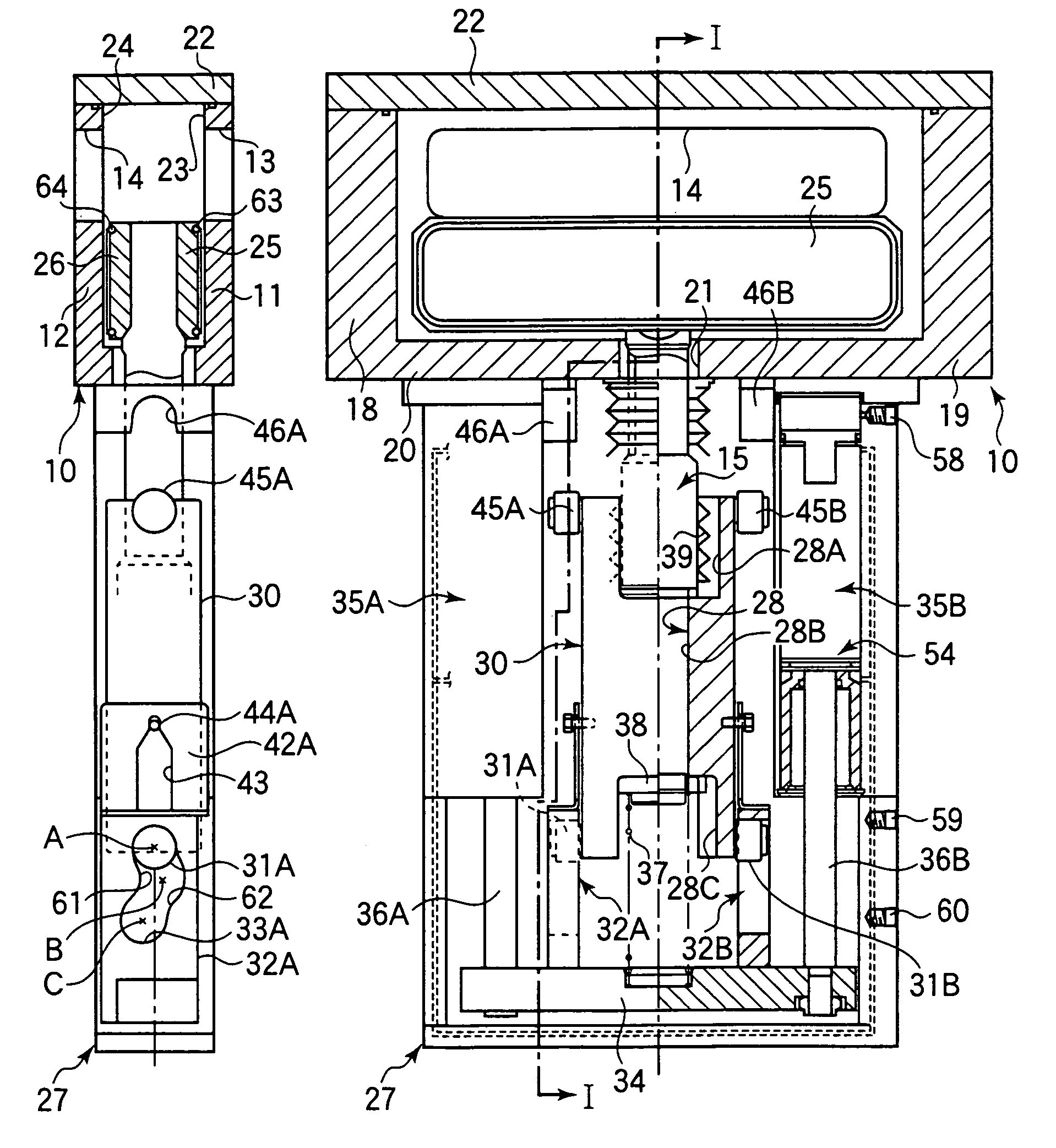
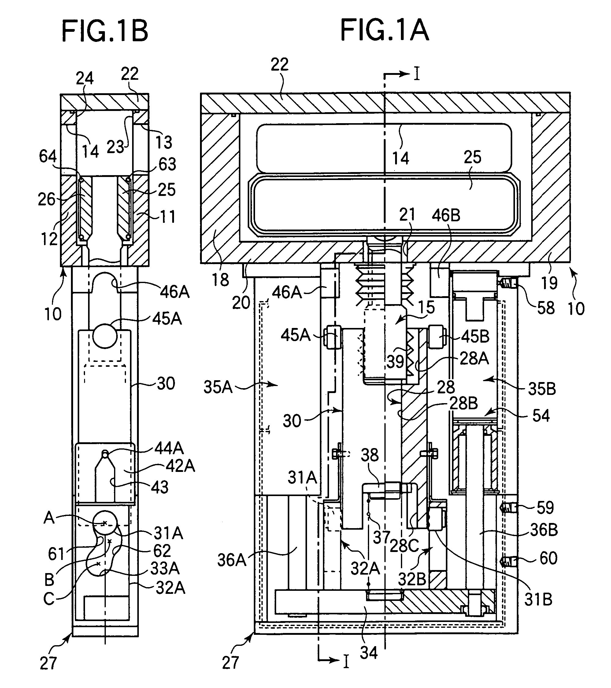
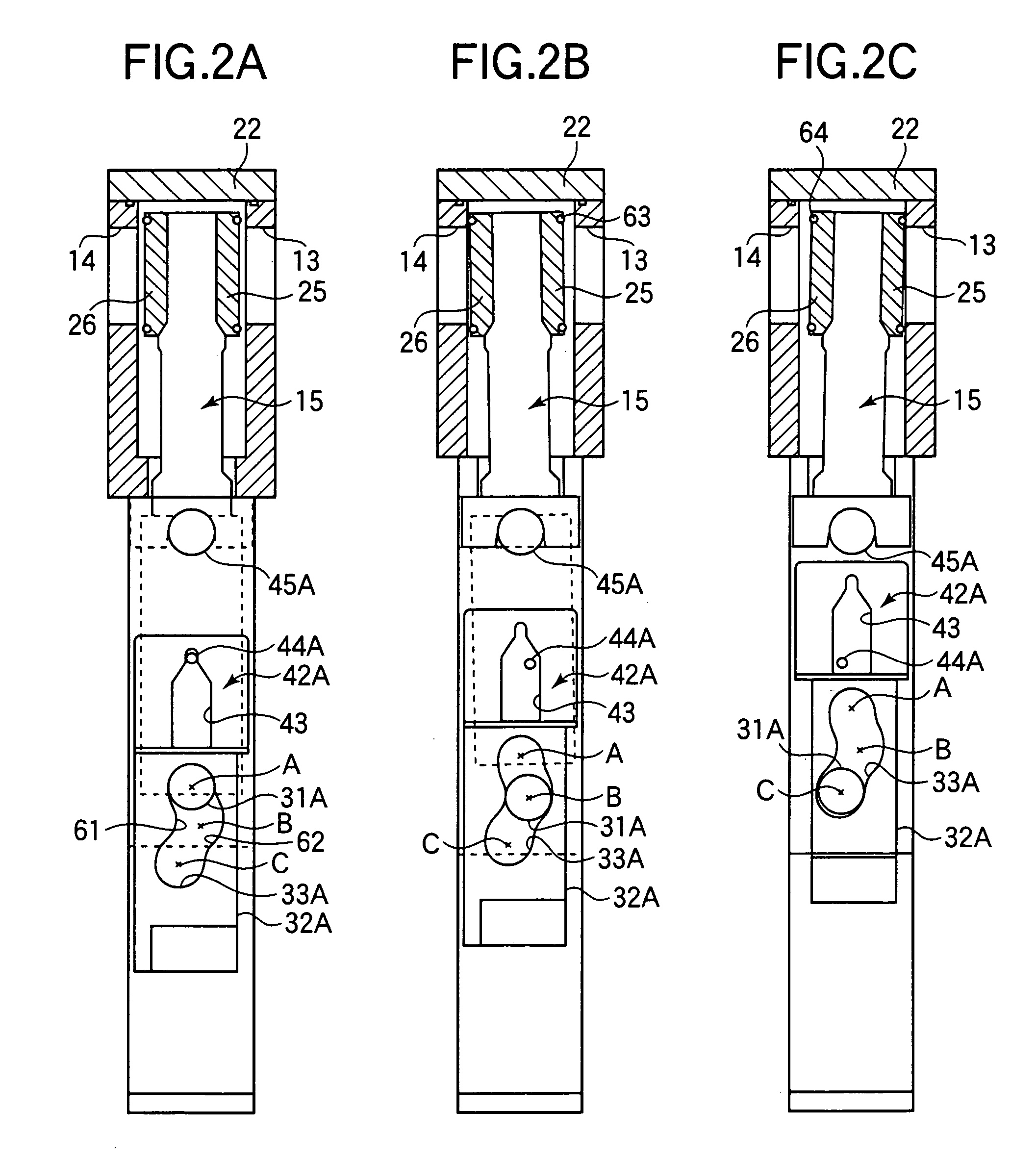
[0042]FIGS. 1A to 7C show embodiments of the gate valve according to the present invention. FIGS. 1A to 3 show a structure for vertically moving and tilting a single shaft 15. As shown in FIGS. 1A and 1B, a gate valve has a valve body 10 comprising a front wall 11, a rear wall 12, a left wall 18, a right wall 19, and a bottom wall 20. A bonnet (cover) 22 is secured to the upper side of the valve body 10. A control body 27 is connected to the lower side of the valve body 10. The gate valve has a TC (transfer chamber) opening 13 in the front wall 11 of the valve body 10 and a PC (process chamber) opening 14 in the rear wall 12. A TC-side valve element 25 and a PC-side valve element 26 are connected to an upper portion 15A of a single shaft 15. The TC-side valve element 25 and the PC-side valve element 26 are disposed in the valve body 10. The upper portion 15A of the single shaft 15 is inserted into an insertion hole 21 in the bottom wall 20. The single shaft 15 extends into the contr...


PUM


Abstract

A gate valve has a transfer chamber-side valve element and a process chamber-side valve element connected to a single shaft actuated with a single three-position air cylinder to selectively close a process chamber opening and a transfer chamber opening or fully open both the openings to allow an object to pass therethrough. A lever member is secured to the single shaft. A roller supported by the lever member is kept in engagement with a cam groove of a cam member. A cam support member for supporting the cam member is connected to the piston rod of the three-position air cylinder. A spring is interposed between the lever member and the cam support member. When the piston rod is in the first (lower extremity) position, both the transfer chamber-side valve element and the process chamber-side valve element fully open the transfer chamber opening and the process chamber opening, respectively. As the piston rod shifts from the first position to the second position, the roller shifts from engagement with an upper position of the cam groove to engagement with an intermediate position, causing the process chamber-side valve element to close the process chamber opening. As the piston rod shifts from the second position to the third (upper extremity) position, the roller shifts from the engagement with the intermediate position to engagement with a lower position of the cam groove, causing the transfer chamber-side valve element to close the transfer chamber opening.

Description

BACKGROUND OF THE INVENTION[0001]1. Field of the Invention[0002]The present invention relates to a gate valve provided between vacuum chambers in a semiconductor manufacturing system, etc., e.g. between a process chamber (hereinafter referred to as “PC”) and a transfer chamber (hereinafter referred to as “TC”).[0003]2. Description of the Related Art[0004]A patent document 1 (U.S. Pat. No. 6,390,448) discloses a gate valve wherein mutually opposing walls of the gate valve body are formed with a PC (process chamber) opening and a TC (transfer chamber) opening, respectively, and the PC opening and the TC opening are selectively closed with a double-sided valve member having a PC-side valve element and a TC-side valve element. With the disclosed technique, for example, the TC opening is closed to keep the transfer chamber at a vacuum while the process chamber is opened to the atmosphere, thereby making it possible to carry out repairs in the process chamber while using the transfer cham...

Claims


Application Information

Patent Timeline
IPC IPC(8): F16K3/10F16K3/14F16K3/16F16K3/18F16K31/524F16K51/02
CPCF16K3/10F16K3/186F16K3/182F16K3/14F16K51/02F16K3/184
Inventor ISHIGAKI, TSUNEO
Owner SMC CORP
Why Eureka
Try Eureka