Ink refill and recharging system

a refilling system and recharging system technology, applied in water installations, thin material processing, construction, etc., can solve the problems of insufficient field irrigation, inability to achieve such advancement, and inability to refill the recharging system, etc., to achieve high level of anisotropy, high reliability, and high level of control of movemen

Inactive Publication Date: 2006-06-27
TUBARC TECH
View PDF66 Cites 1306 Cited by
  • Summary
  • Abstract
  • Description
  • Claims
  • Application Information

AI Technical Summary

Benefits of technology

[0025]It is another aspect of the present invention to provide a tubarc porous microstructure that permits unsaturated fluid to be conducted from a saturated zone to an unsaturated zone and reversibly from an unsaturated zone to a saturated zone.
[0039]The reversible unsaturated siphon of the present invention additionally offers high reliability for bearing a flexible interface of contact, and a high index of hydraulic conductivity and transmissivity. Additional characteristics of the reversible unsaturated siphon of the present invention can include a filtering capability associated with the control of the size of porosity and the intensity of negative pressure applied in the unsaturated zone, a low manufacturing cost, high evaporative surfaces for humidifying effects, and a precise delivery of fluid matric potential for printing systems.

Problems solved by technology

Fluids may also be undesired in places where the fluid is already in place (i.e., drainage).
Field irrigation has not yet attained such advancement because the soil is not connected internally to the hose by any special porous interface.
For unsaturated flow, however, a tube is restricted because it will not permit lateral flow of fluid in the tube walls leading to anisotropic unsaturated flow with a unique longitudinal direction.
This misunderstanding still holds true due to the fact that both capillary tubes and porosity voids are affected by the size of pores to retain and move fluids as unsaturated conditions.
The system becomes even more complex because the fluid-holding capacity of the porosity has a connective effect of inner fluid adhesion-cohesion, pulling the molecules down or up.
One complication is that concepts of unsaturated flow are not as fully developed as those for saturated flow, nor are they as easily applied.” (See Dominico & Schwartz, 1990.
Wiley) Concepts of unsaturated flow have not been fully developed to date, because the “capillary action” utilized to measure the adhesion-cohesion force of porosity is restrained by capillary tube geometry conceptions.
The configuration disclosed in BR P1980367 is limited, because it only permits liquid to flow upward from saturated to unsaturated zones utilizing a capillary device, which implies a type of tubular structure.
Two layers in the conductor have led to malfunctioning by bringing together multiple differential unsaturated porous media, which thereby highly impairs flow connectivity.
All devices using more than one porous physical structure media for movement of unsaturated fluid flow are highly prone to malfunctioning because of the potential for microscopic cracks or interruptions in the unsaturated flow of fluid in the media boundaries.
The one-way capillary conductor disclosed by Silva in Brazilian patent application BR P1980367 fails to perform unsaturated siphoning due to tubing theory and a one-way upward flow arrangement.
A tube is not an appropriate geometrical containing figure for unsaturated flow because it allows fluids to move in and out only by the ends of the hollow cylindrical structure.
A one-way directional flow in a pipe where the fluid has to pass through the ends of the pipe is highly prone to malfunctioning due to clogging, because any suspended particles in the flow may block the entrance when such particles is larger than the entrance.
Unsaturated flow in a conductor cannot possess walls about the tube for containment.
Capillary action operating in a downward direction can lose properties of unsaturated flow because of a saturated siphoning effect, which results from the sealing walls.
The complexity of unsaturated flow is high, as the specialized literature has acknowledged.
Interruption of continuity on pipe walls of saturated flow leads to leaking and reduced flow velocity.
In the case of unsaturated flow interruption in the continuity can be fatal halting completely the flux.
Leaking offers an easy detection feature to impaired saturated flow, but cracking is neither perceptible nor easy to receive remedial measures in time to rescue the unsaturated flow functioning imposed by the sealing walls.
Cubes offer the highest level of surface by volume, but such cubes neither provide a safe void for porosity nor rounding surfaces.
A void in the granular porous structure offers low reliability for continuity because the granules cannot be attached safely to each other and the geometry of the void randomly misses an ensured connectivity.

Method used


Image

  • Ink refill and recharging system
  • Ink refill and recharging system
  • Ink refill and recharging system

Examples


Embodiment Construction

[0090]The particular values and configurations discussed in these non-limiting examples can be varied and are cited merely to illustrate embodiments of the present invention and are not intended to limit the scope of the invention.

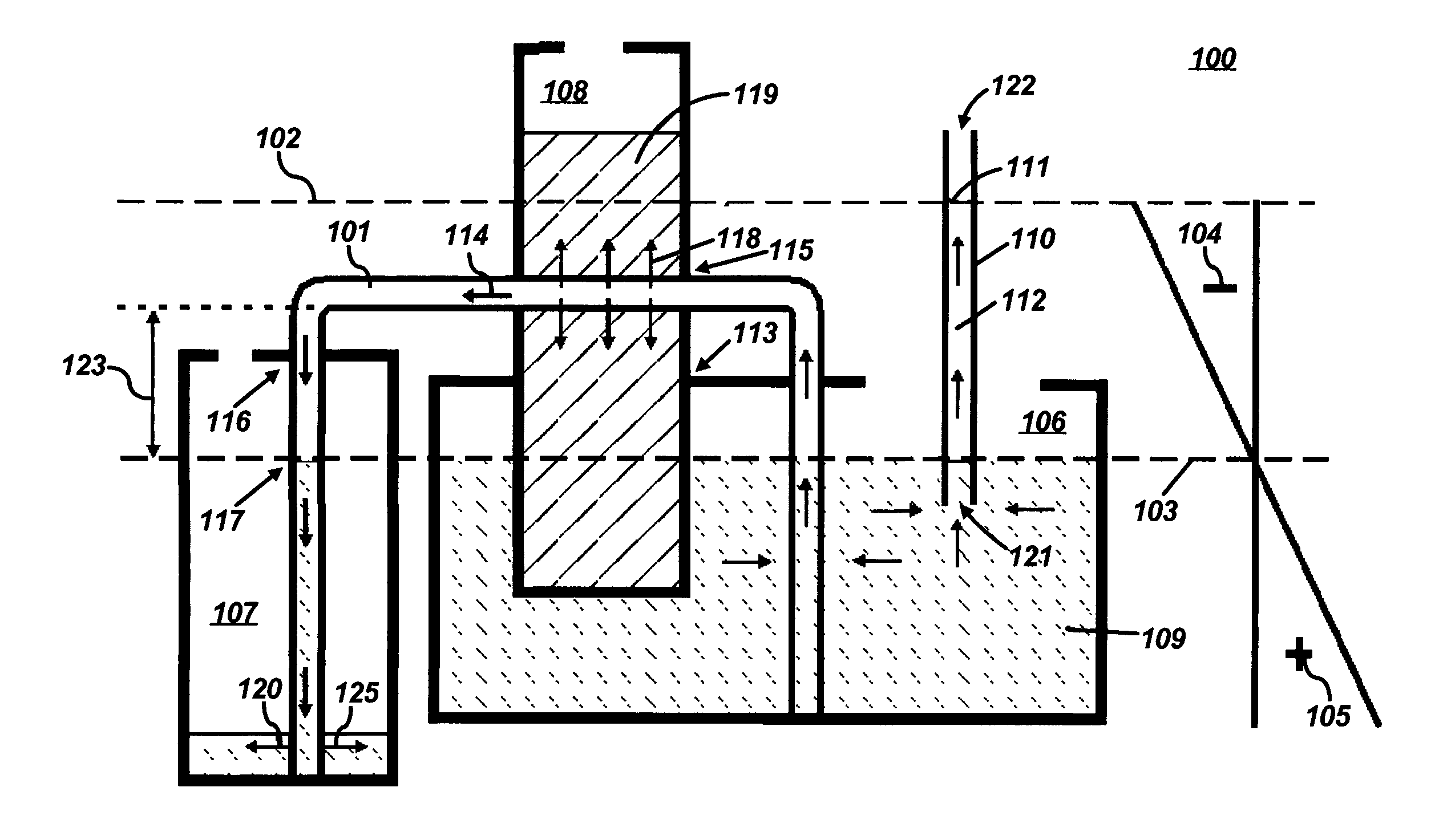
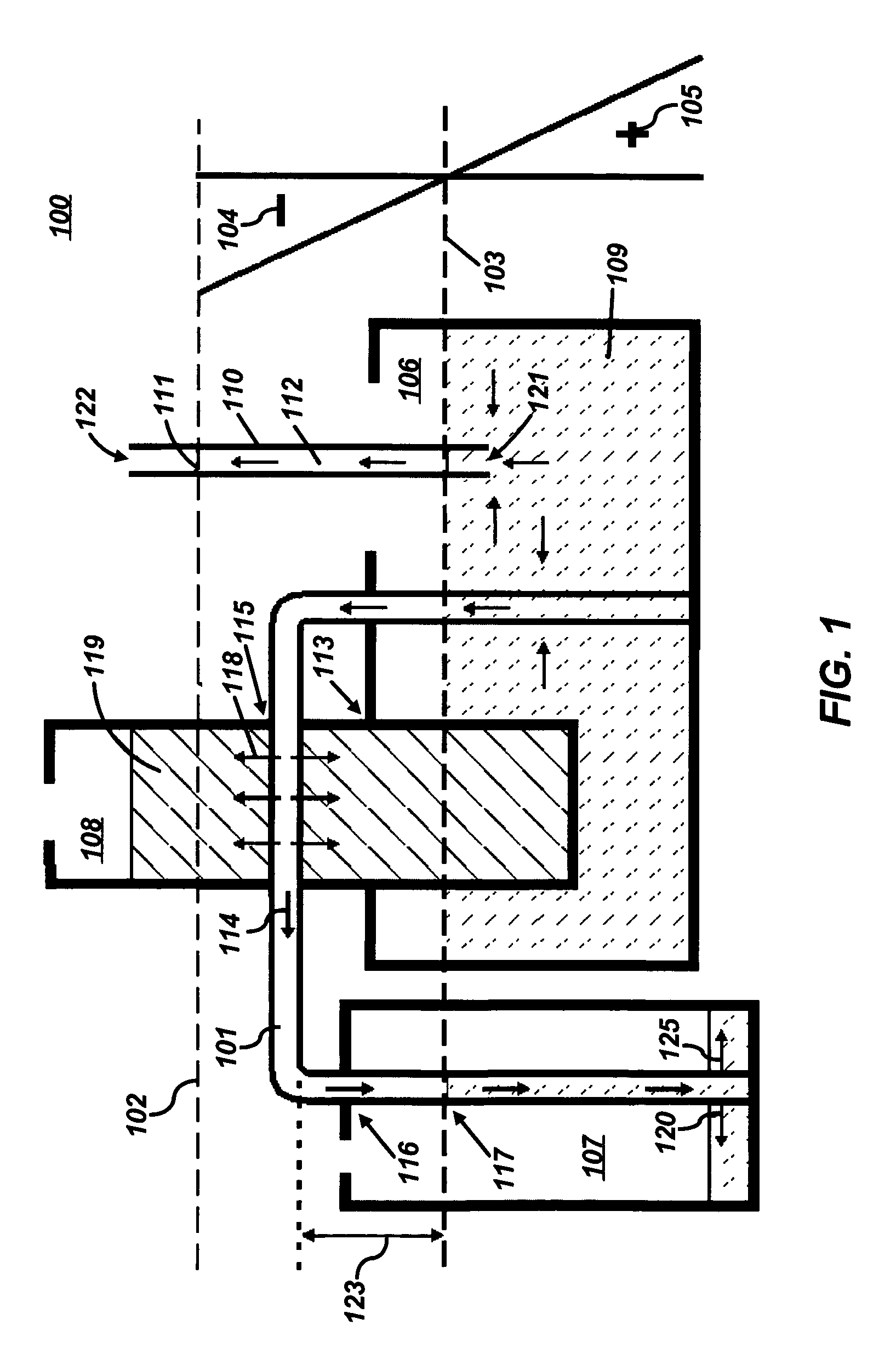
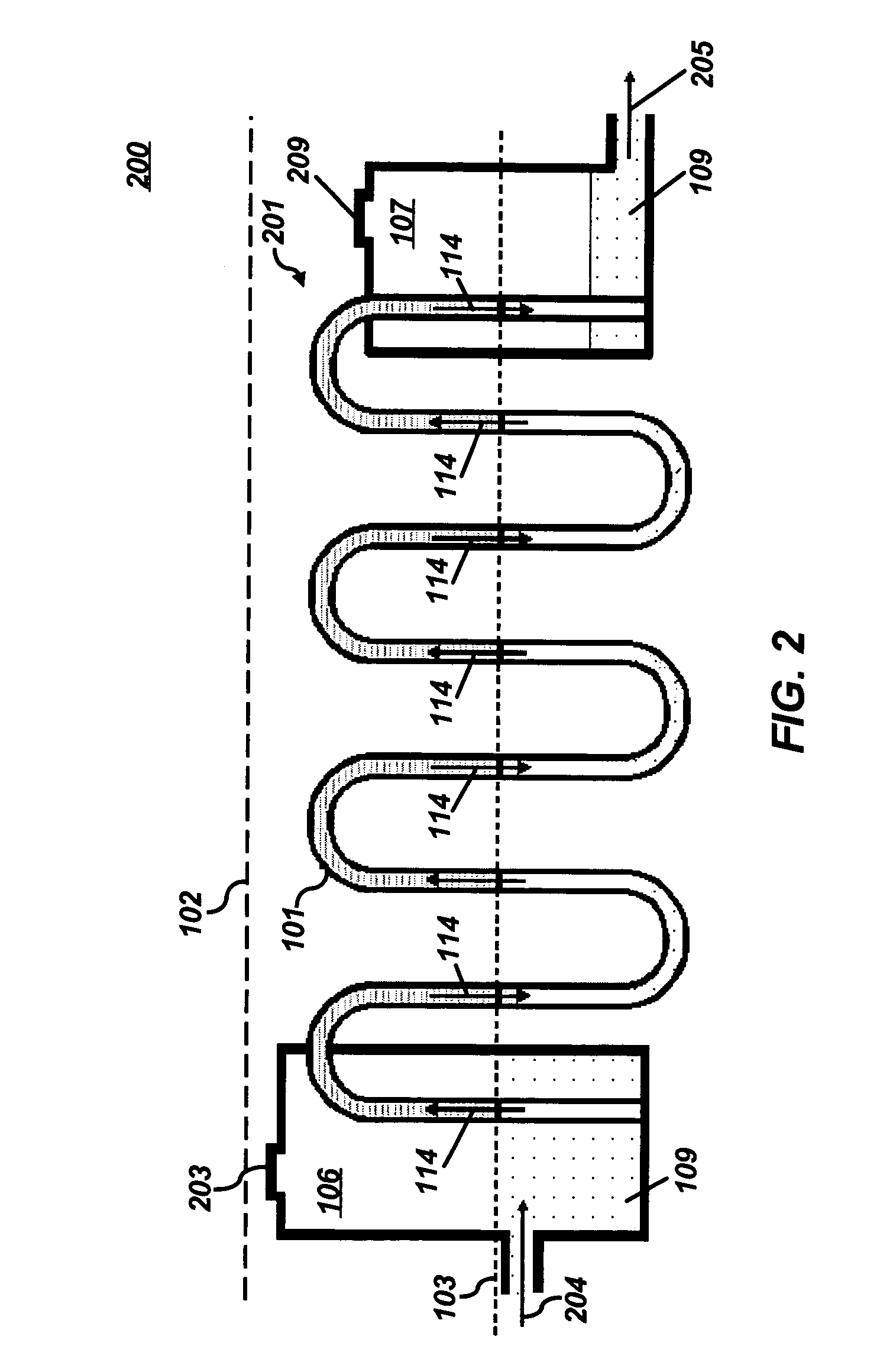
[0091]The figures illustrated herein depict the background construction and functioning of a reversible unsaturated siphon having a porous physical microstructure for multidirectional and optionally reversible unsaturated flow, in accordance with one or more embodiments of the present invention.

[0092]FIG. 1 illustrates a sectional view of a hydrodynamic system 100 illustrating saturation zones and unsaturation zones in accordance with a preferred embodiment of the present invention. Hydrodynamic system 100 illustrated in FIG. 1 is presented in order to depict general capillary rise theory and the functioning of a U-shaped upside down reversible unsaturated siphon 101, which is also illustrated in FIG. 1.

[0093]System 100 of FIG. 1 demonstrates the use of ca...


PUM


Abstract

Ink refill systems are disclosed. In general, an ink source comprising a saturated zone and a tubarc porous microstructure for conducting ink from the saturated zone to an unsaturated zone are provided. The ink can be delivered from the saturated zone to the unsaturated zone through the tubarc porous microstructure, thereby permitting the ink to be harnessed for ink writing and / or printing through the unsaturated hydrodynamic flow of the ink from one zone of saturation or unsaturation to another.

Description

CROSS REFERENCE TO RELATED PATENT APPLICATION[0001]This patent application is a continuation of U.S. patent application Ser. No. 10 / 082,370, “Fluid Conduction Utilizing a Reversible Unsaturated Siphon With Tubarc Porosity Action,” which was filed on Feb. 25, 2002 now U.S. Pat. No. 6,766,817 and claims priority to U.S. Provisional Patent Application Ser. No. 60 / 307,800, which was filed on Jul. 25, 2001. The disclosure of U.S. patent application Ser. No. 10 / 082,370 is incorporated herein by reference.TECHNICAL FIELD[0002]Embodiments are generally related to fluid delivery methods and systems. Embodiments are also relates to methods and systems for hydrodynamically harnessing the unsaturated flow of fluid. Embodiments are additionally related to the geometry of physical macro and microstructures of porosity for fluid conduction and retention. Embodiments are also related to ink refill and recharging methods and systems.BACKGROUND OF THE INVENTION[0003]Fluid delivery methods and systems...

Claims


Application Information

Patent Timeline
Patent Type & Authority Patents(United States)
IPC IPC(8): B41J2/175E03B1/00
CPCB41J2/17509Y10T137/0318Y10T137/2774Y10T137/2842
Inventor DA SILVA, ELSON DIAS
Owner TUBARC TECH
Why Eureka
Try Eureka